
Instruction Manual


Spark Plug Wires
High quality, spiral wound wire and proper
routing are essential to the operation of the
SPORT 6 Ignition Control. This type of wire
provides a good path for the spark to follow
while minimizing electromagnetic
interference (EMI).
NOTE: Do not use solid core spark plug
wires with the SPORT 6 Ignition Control.
Routing
Wires should be routed away from sharp
edges, moving objects, and heat sources.
Wires that are next to each other in the
engine’s firing order should be separated.
For example, in a Chevy V8 with a firing order
of 1-8-4-3-6-5-7-2, the #5 and #7 cylinders
are positioned next to each other on the
engine as well as in the firing order. Voltage
from the #5 wire could jump to the #7 wire.
This could cause detonation and engine
damage. For added protection against
cross-fire, Mallory offers PRO SHIELD
insulated sleeving. Pro Shield is a glass
woven, silicone coated protective sleeve
that slides over your plug wires. It also
helps reduce damage from heat and
sharp objects.
MISCELLANEOUS INFORMATION
Sealing
Do not attempt to seal the SPORT 6 Ignition
Control. All of the circuits of a SPORT 6
receive a conformal coating of sealant that
protects the electronics from moisture. Sealing
the SPORT 6 will not allow any moisture that
seeps in through the grommets to drain and
may result in corrosion.
Welding
To avoid any damage to the SPORT 6
Ignition Control when welding on the vehicle,
disconnect the positive (red) and negative
(black) power cables of the SPORT 6 Ignition
Control. It is also a good idea to disconnect
the tachometer ground wire as well.
Distributor Cap and Rotor
We recommend installing a new distributor
cap and rotor when installing the SPORT 6
Ignition Control. Be sure the cap is clean
inside and out, especially the terminals and
rotor tip. On vehicles with smaller caps, it is
possible for the air inside the cap to become
electrically charged causing crossfire which
can result in misfire. You can prevent this by
drilling a couple of vent holes in the cap.
Drill the holes between terminals at rotor
height, facing away from the intake. If needed,
place a small piece of screen over the holes
to act as a filter.
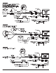
SPORT 6 Diagnostic LED
On the end panel of your SPORT 6 ignition
there is a small hole. Behind this hole is a
red LED indicator. This serves two purposes:
when you first turn on the ignition switch,
the LED will flash rapidly 3 times. This
indicates that the ignition system has power,
and that the microprocessor is running properly.
In addition, the LED will flash when receiving
a proper trigger signal from the vehicle. If,
after a normal power-up, the LED doesn’t
flash when cranking the engine, you should
check your triggering circuit for problems. If
the LED flashes when the engine is cranked,
but there is still no spark, the problem lies
somewhere else.
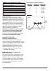
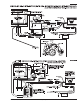
MOUNTING
The SPORT 6 Ignition Control can be
mounted in any position. If you mount it in
the engine compartment, keep it away from
moisture, moving objects and heat sources.
Do not mount the unit in an enclosed area,
such as the glove box. When you find a
suitable location to mount the unit, make
sure all wires of the ignition reach their
connections. Hold the ignition in place and
mark the location of the mounting holes.
Use a 1/8" drill bit to drill the holes. Use the
supplied self-tapping screws to mount the
box. Mounting it horizontally or with the
wiring down is preferred.
2 www.malloryracing.com MALLORY IGNITION