
Instruction Manual


3MALLORY IGNITION www.malloryracing.com
WIRING
Wire Length
All of the wires of the SPORT 6 Ignition
Control may be shortened as long as quality
connectors are used or soldered in place.
To lengthen the wires, use one size larger
gauge wire (12 gauge for power leads, 16
gauge for all others). Use the proper
connectors to terminate all wires. All
connections must be soldered and sealed.
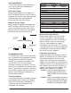
Grounds
A poor ground connection can cause many
frustrating problems. When a wire is
specified to go to ground, connect it to the
chassis. Always connect a ground strap
between the engine and chassis. Connect
any ground wires to a clean, paint-free
metal surface.
Ballast Resistor
If your vehicle has a ballast resistor in line
with the coil wiring, it is not necessary to
bypass it. This is because the SPORT 6
Ignition Control receives its main power
directly from the battery.
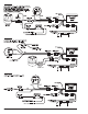
WIRE FUNCTIONS
Power Leads – 2 Pin Weatherproof
Connector
The two heavy gauge wires (14 gauge) that
deliver battery voltage to the ignition:
Heavy Red Connects directly to the battery
positive (+) terminal or to a positive
battery junction. It could also be
connected to the positive side of the
starter solenoid. NOTE: Never
connect this wire to the alternator.
Heavy Black Connects to frame or chassis ground.
Trigger and Coil Leads – 4 Pin
Weatherproof Connector
Red Connects to a switched 12 volt source,
such as the ignition key.
Yellow Connects to the positive (+) terminal of the
coil. NOTE: This is the only wire that makes
electrical contact with the coil positive
(+) terminal.
Black Connects to the negative (–) terminal of the
coil. NOTE: This is the only wire that makes
electrical contact with the coil negative
(–) terminal.
Green Connects to points, electronic ignition
amplifier output or to the green wire of a
Mallory timing accessory. When this wire is
used, the magnetic pickup connector is not
used.
Additional Individual Wires:
Yellow Connects to the tachometer.
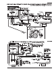
Trigger Wires
Either of two circuits will trigger the SPORT
6 Ignition Control: a points circuit (green
wire) or a magnetic pickup circuit (violet and
green wires).
NOTE: The two circuits must never be
used together.
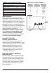
Violet/Green These wires are routed together in
one harness to form the magnetic
pickup connector. The connector
plugs directly into a Mallory distributor
or crank trigger. It will also connect to
factory magnetic pickups or other
aftermarket pickups. The violet wire is
positive (+) and the green is negative
(–). When these wires are used, the
white wire is not used. Consult the
chart that shows the polarity of other
common magnetic pickups.