
Instruction Manual


4 www.malloryracing.com MALLORY IGNITION
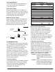
Rotary Switch Position Examples:
Switch #1
Switch #2 RPM Limit
1 0 1,000
2 4 2,400
2 5 2,500
6 0 6,000
7 8 7,800
9 9 9,900
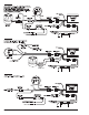
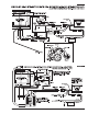
ROUTING WIRES
Route all wires away from heat sources,
sharp edges, and moving objects. Route the
trigger wires separate from the other wires
and spark plug wires. If possible, route them
along a ground plane, such as the block or
firewall, which creates an electrical shield.
The magnetic pickup wires should be routed
separately and twisted together to help
reduce extraneous interference.
WARNING: The SPORT 6 Ignition Control
is a capacitive discharge ignition. High
voltage is present at the coil primary
terminals. Do not touch these terminals
or connect test equipment to them.
PRESTART CHECKLIST
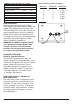
SPORT 6 Cylinder Selection
Your SPORT 6 Ignition comes from the
factory set up for 8 cylinder operation. If you
want to use this ignition with a 4 or 6 cylinder
engine, rotate the center rotary switch,
accessible through the end plate, to the
proper number of cylinders. To select the
4 cylinder mode, turn the switch to the
“4” position. See Figure 1.
RPM Limiter Settings - 6863M only
Main RPM Limiter
The main RPM Limiter is adjusted by using
the pair of switches on the left side of the
end plate. The left switch of the pair is for
1,000’s and right is for 100’s. To eliminate
the RPM Limiter, simply rotate the switches
to a setting above the engine’s maximum
RPM. See Figure 1.
COMMON COLORS FOR MAG PICKUP WIRES
Distributor Mag + Mag –
Mallory Crank Trigger Purple Green
Mallory Billet Competition Distributor,
Series Nos. 81 and 84 Orange Purple
Mallory COMP
®
9000 Series Nos. 96-99
Orange Purple
Mallory Harness P/N 29040 Red Black
MSD Orange/Black Violet/Black
MSD Crank Trigger Orange/Black Violet/Black
Ford Orange Purple
Chrysler Orange/White Black
FIGURE 1
MAIN
RPM
LIMITER
CYLINDER
SELECT
LED
1
2
3
4
5
6
7
8
9
0
1
2
3
4
5
6
7
8
9
0
1
2
3
4
5
6
7
8
9
0