888-230-2225 help@manhattancomfort.
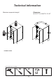
Technical information Maximum supported weight Dimension: W: 26.77" H: 46.46" D: 21.
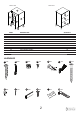
FRONT VIEW REAR VIEW 01 04 09 10 06 03 07 02 09 11 05 07 08 08 08 PART 01 02 03 04 05 06 07 08 09 10 11 QUANTITY 01 01 01 01 01 01 02 04 02 01 01 DESCRIPTION TOP RIGHT SIDE SHELF LEFT SIDE BASE BACK COVER (DRILLED) BACK COVER FEET ADJUSTABLE SHELF LEFT DOOR RIGHT DOOR HARDWARE A 16x B 04x C 04x D 16x E 01x F 04x H 08x I 34x J 02x K 02x L 01x M 01x E U GL 2 G 01x
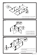
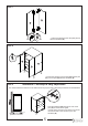
STEP 1 B B 08x H B H 01 H B H 04 H H H B H 02 H 04x - Insert the hardware (H) into the parts (02, 04). - Insert the hardware (B) into the part (01). STEP 2 C 02x C A A 01 02x C 02 03 - Connect the part (02) onto the part (01) with the hardware (C). - Connect the part (03) onto the part (02) with the hardware (A). STEP 3 C A C 02x 01 C 04 03 A 02 05 A A A 06x - Connect the part (04) onto the parts (01, 03) with the hardware (C+A).
STEP 4 I 34x 06 07 07 J 02x - Connect the parts (06, 07) with the hardware (I+J). STEP 5 USE THE GLUE (L) BEFORE FASTENING THE FEET (08). A 08 A L 08 05 A 08x 08 08 08 - Connect the parts (08) under the part (05) with the hardware (A). STEP 6 09 09 - Insert the parts (09) as showed above.
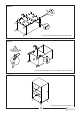
STEP 7 F F D D D D 11 10 F F D D F D D D - Connect the hinges (F) into the parts (10, 11) with the hardware (D). 08x 04x STEP 8 D D 04 D 08x 10 02 D D 11 - Connect the part (11) onto the part (02) and the part (10) onto the part (04) with the hardware (D). STEP 9 Attention! This step is very important! You need to attach the furniture on the wall to avoid any tip over risk. Follow the procedures as showed below.
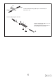
E wings *Press the hardware wings (E) to put in the hole that you drilled in the wall. wings Hardware (E), plugged in the wall. E M Connect the hardware (M) onto the wall with the hardware (G). Then fasten with the hardware (K) the hardware (M) on the part (01).