
Owners Manual


A METER CAL - GR ACCURACY
1. Supply a line level input signal 1K TONE @ 0 VU (or between 1 and 1.5 volts)(0 VU = 1.228 volts )
2. Adjust front controls for NO LIMITING
3. Back down the reduction control to achieve 6dB of actual limiting as observed on an external VU meter or AC
volt meter. 6 dB of limiting will reduce the volts by 1/2. If you start with 1 volt expect .5 volts after limiting 6dB.
4. Adjust each channel's trimpot located on the extreme back corners on the main circuit board.
B METER - Adjusts meter "ZERO". Needs to be well warmed up. This simply sets meter "rest" position.
1. Set in Limit Mode. No Signal
2. Adjust front panel METER ADJUST so that meter reads ZERO gain reduction.
The above adjustments interact - You may want to repeat these two steps for best accuracy.
C 3. COMPRESS TRIM - Also adjusts meter ZERO but in compress mode. Stable & unlikely to need adjustment.
4. Locate the internal trimmers directly next to the meters.
5. Switch to COMPRESS and adjust trimmer for ZERO on the meter.
D. To adjust internal balance and lowest distortion: We recommend that this control be reset only after
changing 5670 tubes. This is not Left /Right balance. This "balance" sets the relative gains of the 2
halves of a differential circuit. Exact balance = lowest distortion & thumps. Step E sets the balance
further down the path. Another method for well equiped techs, is to use a distortion analyser.
1. Adjusting the front panel BALANCE control balances the current draw of the 5670 cathodes.
2. Set a multimeter to read DC volts and connect the probes to the two test points below the GR
Meters. Expect a very small voltage, this is a "null adjustment"
3. Adjust the small trim pot located on the front panel and marked "ADJUST" until the METER nulls to zero.
E 5. This procedure is best done by ear with loud drum tracks. Set Attack and Recovery for fastest settings and at
least 6 dB of Limiting. Start the trimmer at center and while listening carefully to the output adjust the trim for
minimum "thumping". We select 5670's to minimise this. Trim procedure "D" also affects "thumping". The best
procedure involves all of these.
These are factory presets. These should only be altered after a re-tube.
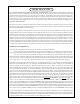
SERVICE ADJUSTMENTS
15
IEC RECEPTACLE
FUSEHOLDER
12 VDC
REGULATOR
12 VDC
REGULATOR
POWER
TRANSFORMER
OUTPUT
TRANSFORMER
OUTPUT
TRANSFORMER
REG REG
CH1 INPUT
TRANSFORMER
CH2 INPUT
TRANSFORMER
5670
5751
7044
12AL5 12AL5
7044
5751
5670
BALANCE BALANCE
METER METER
COMPRESS
ZERO TRIM
COMPRESS
ZERO TRIM
A
A
B
B
C
C
D D
E
E