
Owners Manual


MANLEY
LABORATORIES INC.
REDUCTION dB
6
0
2
4
8
10
12
IN
BYPASS BALANCE
LIMIT
COMPRESS
RECOVERY
SLOW FAST
THRESHOLD
MIN MAX
OUTPUT
ATTACK
SLOW FAST
SEP LINK
POWER
DUAL INPUT
ADJUST METER
METER
ADJUST
ATTACK
OUTPUT
THRESHOLD
RECOVERY
COMPRESS
LIMIT
BALANCE
BYPASS
IN
MANLEY
LABORATORIES INC.
REDUCTION dB
6
0
2
4
8
10
12
MANLEYSTEREO "VARIABLE-MU" LIMITER COMPRESSOR
FASTSLOW
MAXMINFASTSLOW
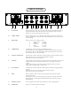
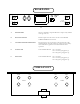
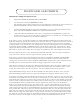
FRONT PANEL
A H B C D E F G H I E F C D B H A
6
A IN / BYPASS Switched in bypass mode, (down position) all effects of the limiting circuitry are
bypassed and will not affect the audio signal. In the bypass mode , the audio
signal passes from the input directly to the output.
B. COMP. / LIMIT Selects compression ( 1.5:1) or limiting (4:1) function. Compression is soft -knee,
Limit is a sharper knee. At greater than 12dB of limiting the ratio increases (up to
20:1 maximum)
C. RECOVERY Recovery times can be selected between
a. VERY SLOW 8 seconds
b. SLOW 4 seconds
c. MEDIUM .6 seconds
d. FAST .4 second
e. VERY FAST .2 second
D. THRESHOLD Continuously variable gain reduction threshold control.
Determines the necessary amplitude for compression or limiting to take effect.
Most extreme effect is at the MIN (fully counter clockwise) position. The lower
the threshold, the more that gets limited.
E. OUTPUT ATTENUATE Continuously variable attenuation of output signal leaving the amplifier circuitry.
Full attenuation occurs at the full counterclockwise position.
This control is active only in IN mode.
F. ATTACK Continuously variable sensitivity of transient detection. Determines the necessary
length of transient to initiate gain reduction. Fast =25mS, Med =50mS, Slow
=70mS.
Fully counter clockwise at the slowest setting will prevent most percussive
signals from causing limiting or compression.
G. DUAL INPUT Continuously variable attenuation of input signal entering the amplifier limiting
circuitry
Full attenuation occurs at the fully counterclockwise position.
This control is active only in IN mode.
I. LINK When switched to "SEP" left side is independent from the right side. When
switched to "LINK"
both channels are reduced in gain by the same number of dB. This insures that
the stereo image is unchanged. The METERs remain independent to help set
THRESHOLDs.
I. POWER ON/OFF Power is supplied to the unit when switched UP. Meters will illuminate
H. GR METER Measures in decibels amount of reduction