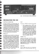
II -II ....._ R Model 2210 Stereop.honic Receiver MARANTZ CO., INC. ' P.O. BOX 99· SUN VALLEY, CALIFORNIA' 91352 A WHOLLY-OWNED SUBSIDIARY OF SUPERSCOPE INC.
~RRAN ,.A II parts of MARANTZ products are fu lly gU!Jranteed for a.pericd of THREE YEARS fr om date of ' purchase, except fo r t ubes Wh ich are gua rant eed for NINETY DAYS f ro m date of purchase, and except fo r speaker prod ucts.
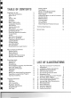
TABLE OF CONTENTS Preparation for Use Rear Panel Connections Phono 1 & 2 Play Record 1 & 2 Auxiliary Quadradial Main In and Pre Out Loudspeaker Systems FM Antenna Antenna Attenuator AM Antenna Connection to AC Outlet Convenience Outlet Simplified Operating Procedure Tuning Meters Tuning FM Antenna Orientation Mono In (L, R) Switch Tape/Source Monitor Switch Loudness Switch Hi-Blend Switch Low Filter Switch Hi Filter Switch Muting Switch and Level Control 2 2 2 2 2 2 3 3 3 4 5 5 5 5 5 6 6 6 6 6 6 6 7 7 7 M
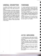
GE E AL OESC PTON F EWORO Your Marantz Model 2270 all solid state receiver incorporates the advanced circuitry for which Marantz is famous in the audio component in dustry. Unparalled technology and innovation made poss i ble this combination of three superb component sections on a single chassis : Tuner, Preamplifier, and Power Amplifier. Internal connections between these component sections ensure optimum per formance from each section, and retain the full flexibility of separate components.
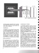
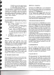
Figure 1. Rear Panel Connection Facilities and Adjustments PREPARATION FOR USE REAR PANEL CONNECTIONS PLAY All signal connections to the Model 2270, with the exception of the FM antenna and loudspeakers, should be made with shielded audio cables. Figure 1 shows the location of input and output jacks on the rear panel. These jacks are for "permanent" connections. Front panel jacks and their use will be discussed later. The rear panel signal connections are arranged in stereo pairs.
,q- S'VlSTEM 1 ~ E PEA T WIRtNG AS FOR SYSTEM 1 Figure 2. loudspeaker System Connections contained playback preamplifiers. phono cartridges with RIAA-equalized high-level output, additional tuners and/or receivers, TV sound outputs, and other external components. aUADRADIAL In anticipation of the coming of 4-channel stereo broadcasting, your Model 2270 is equipped with an output aUADRADIAL jack. The signal avai lable at this jack is the unequalized, buffered output of the FM discriminator.
dard zipcord will reveal some form of coding on the insulation, e.g., ridge or groove on one edge, one of the wires may be "silver" while the other is bare copper.) Coded wires help insure identical connections for each channel. For each channel, the coded wire can be connected between the "common" terminal of your loud speaker and the GROUD terminal of the ampli fier channel. The remaining uncoded wire is then connected between the remaining loudspeaker and amplifier terminals.
CONNECTION TO AC OUTLET With the front panel power pushswitch "out," plug the line cord into an electrical outlet supplying the proper voltage. CAUTION: DO NOT PLUG YOUR MODEL 2270 INTO A DCOUTLET SINCE SERIOUS DAMAGE WILL OCCUR. Figure 4. AM Ferrite-rod Antenna CONVENIENCE OUTLET One UNSWITCHED and one SWITCHED AC OUTLET are provided on the rear panel for powering associated components of your system (tape recorder, record player, etc.).
TUNING knob until the desired station is tuned. Adjust the volume control for comfortable listening volume. The tuner section of the Model 2270 is equipped with electronically triggered circuits which auto matically mute interstation noise and automati cally switch to the proper mode of operation for stereo and monophonic FM broadcasts. In addition, the STE REO indicator light automatically indi cates a stereo broadcast.
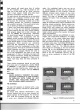
- - -- --------- - -- . . - ~ - - - - - - - -- ~~ I:t.'~~"'I ".~~~_~:~ lit r1 U •i III EJl •• • I' ~" I _ ,u_.: _ I - - - - - - -. ~ ----- .• t,) -- ~. , ~ - -- - - - - - - - - -:JG . '"'" CC o. _ . @) • . •..p, • '.", . .,-:,\:. ~~---:.-_------'--------.r- figure 5. front Panel Controls and Jacks MAIN CONTROLS AND WIT HES LOW FILTER SWITCH SELECTOR SWITCH The low frequency filter can be used to reduce turntable rumble and low frequency noise.
BASS, MID AND TREBLE CONTROLS LEFT CH A N NE L I These controls are used to adjust the tonal balance of program material to suit your individual listen ing preference. Each control is of the dual con centric friction -coupled type. This permits sepa rate control of each channel to compensate for unbalanced room acoustics or for any other tonal imbalance in program material. The friction-coupled feature conveniently allows simultaneous adjust ment of both channels.
RECORDING To make a recording, set the selector switch to the desired program source and put the recorder into the "record" mode of operation. With the MON I TOR (TAPE/SOURCE) pushswitch in the "out" position, the or iginal program source will be heard. Depress the MONITOR (TAPE/SOURCE) pushswi tch to hear the "results" of the recording while it is in progress.
To copy from the main 1 (or main 2) recorder to the external recorder: 1. Disconnect the plug from the dubbing IN jack. 2. Set the selector switch to "TAPE" and the MONITOR (TAPE/SOURCE) pushswitch to "out" position. 3. Put the main 1 (or main 2) recorder into the playback mode and the external recorder into the record mode. 4. Put MONITOR pushswitch into 1 (or 2) po sition . To copy from the external recorder to the main 1 (or main 2) recorder: 1. Insert the plug into the dubbing IN jack. 2.
FRONT END FM antenna signals are applied through a balun transformer and the antenna attenuator switch to the antenna coil which drives a field-effect transis tor RF amplifier. When the ATTENUATOR push switch is placed in the "OUT" position, the attenu ator circuit is cut off and FM signals are directly fed to the FM antenna coil. With ATTENUATOR switch placed in the "IN" position, the signals are attenuated about 20dB by the attenuator circuit, then fed to the antenna coil.
"pop" noise for smooth tune in and tune out. AM TUNER The AM tuner portion of the Model 2270 has been provided with a tuned R F amplifier incorporating a three-section variable capacitor for improved selectivity and spurious response. The ceramic filters utilized in the AM IF amp lifier have very high selectivity and adequate bandwidth for interference-free AM reception. Following the AM IF amplifier, the AM detector re covers the audio modulation and provides this sig na l to the selector switch.
change of attenuation in each channel as the control is turned away from center has been designed to maintain total apparent loudness from both channels. This feature makes it a true stereo balance control. VOLUME CONTROL The volume control attenuates both channels simultaneously and maintains tracking to within 3dB at any point of attenuation to -SOd B from maximum.
100Hz 20Hz 1KHz 10KHz Figure 9. Phono Equalization Characteristics Figure 10.
0.1 KHz 10KHz 1KHz Figure 11 . Low and High Filter Characteristics Figure 12.
9L MOOL MOL ML ML ·O ~:""':":"'-r.-~-n::- ......, ~----:~:-:r: :":"'"'"':r--:-:: ....-:' ::----:':" ----, % LO·O = ==J %L"O UO!1eJedas oaJa1S 'r l aJn6!:i zH)lOL ZHOOL ZH 09 r--i;or-----r;~i""il"'"iI....-. ...__;~-....._--____r:''''i':'"l':''"'T':''_:_:_-_::_:_......
-2 -6 1~:=== - 8 1~ ~ 10Hz 17 100Hz 10KHz 100KHz Figure 15.
TECHNICAL SPECIFICATIONS AUDIO CIRCUITS: Rated continuous (RMS) power output per channel, both channels operating simultaneously, 20Hz to 20,OOOHz 70 Watts at 4 and 8 ohms 40 Watts at 16 ohms Comparable Total Music Power (I H F) 210 Watts at 8 ohms High-level hum and noise (ref. 40W at 8 ohms). . . . . . . . . . . . . . . . . . . . . . . . . . . . . . . -80 dB Phono hum and noise 1.5 f.1. V equivalent input Dynamic range (phono input to tape recording output) 96dB I. M.
Please Pack the Receiver as Illustrated. CAUTION Please DO NOT ship your receiver mounted in its accessory walnut cabinet. Insure receiver for full value : Make sure that your correct return address is on shipping label. Ship via PARCEL carrier. a reputable carrier. (DO NOT USE POST)Be sure to obtain receipt from SERV CE NOT S REPAIRS Only the most competent and qualified service technicians should be allowed to service the Mar antz Model 2270 Receiver.