
Instruction manual
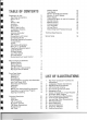

TABLE
OF
CONTENTS
Preparation
for
Use 2
Rear
Panel
Connections 2
Phono 1
& 2 2
Play 2
Record 1
& 2 2
Auxiliary
2
Quadradial 3
Main In and Pre
Out
3
Loudspeaker Systems 3
FM Antenna 4
Antenna
Attenuator
5
AM Antenna 5
Connection
to
AC
Outlet
5
Convenience Outlet 5
Simplif
ied Operating Procedure 5
Tuning Meters 6
Tuning 6
FM Antenna Orientation 6
Mono In (L, R) Switch 6
Tape/Source
Monitor
Switch 6
Loudness Switch 6
Hi-Blend Switch 6
Low
Filter
Switch 7
Hi
Filter
Switch 7
Muting Switch and Level Control 7
Main Controls and Switches
Sel
ector Switch
Balance Control
Volume Control
Bass
Mid and Treb le Controls
Main-Spkr-Remote Switch
Front
Panel Jacks 8
Dubbing Out 8
Dubbing In 8
Stereophones 8
Some Suggestion on Using Tape Recorders
with
Your
Model 2270 8
Recording and Playback 8
Recording 9
Playback 9
Making
Two
Recordings Simu ltaneously 9
Recording a Long-Duration Program 9
Copying and Editing 9
Technical Description 10
General 10
Front
End 11
FM IF
Amplifier
11
Multipath Indicator 11
FM Stereo Demodulator 11
Muting Circuit 11
AM Tuner 12
7
7
7
7
8
8
Selector Switch 12
Tape Signals 12
Monitor
(Tape/Source) Switch 12
Monitor
(1 and 2) Switch 12
Phono Signals 12
Hi Blend and Mono (L and R) Functions 12
Control Circuits 12
Balance Control 12
Volume
Control 13
Tone
Amplifier
13
Hi-Low
Filters 13
Output
Stage and Protective Circuits 13
Technical Specifications 18
Service Notes 19
LIST
OF
ILLUSTRATIONS
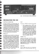
1. Rear
Pane
l Connection Facilities and
~ustme~
2
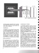
2. Loudspeaker System Connections 3
3.
FM/
AM Antenna Connect ion 4
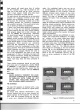
4. AM Ferrite-rod Antenna 5
5.
Front
Panel Controls and Jacks 7
6. Stereophone Plug 8
7. General Arrangement
of
Tape Recorder 9
8. Functional Block Diagram 10
9. Phono Equalization Characteristics 14
10. Tone Control Characteristics 14
11. Low and High
Filter
Characteristics 15
12. FM Characteristics 15
13. Stereo Separation 16
14. Harmonic Distortion 16
15. Frequency
Response
17
16. Packing Instructions 19