
Instruction manual

PREPARATION
FOR
USE
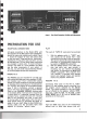
REAR PANEL CONNECTIONS
All signal
connections
to
the
Model 2270, with
the
exception
of
the
FM
antenna
and
loudspeakers,
should be made with shielded
audio
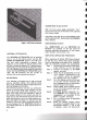
cables. Figure
1 shows
the
location of
input
and
output
jacks
on
the
rear panel. These jacks are for
"permanent"
connections.
Front
panel jacks and
their
use will
be discussed later.
The
rear panel signal
connections
are arranged in stereo pairs. To avoid confusion,
connect
one
cable
at
a
time
between
the
2270
and
the
other
components
of
your
system. In
this way, you will avoid cross-connecting channels
or confusing signal sources with destinations.
PHONO 1
& 2
The
PHONO jacks are
intended
for
use with mag-
netic
phono
cartridges requiring a
standard
47,000-
-
ohm
resistive load. If
hum
is heard when playing
records, it is usually evidence of improper grounding
or shielding of
the
record player or its
connections
.
Try
reversing
the
polarity of
the
turntable's
power
plug. If this is ineffective,
connect
a separate
ground wire from
the
turntable
or record changer
frame
to
the
CHASSIS GROUND binding posts
of
the
Model
2270.
If
the
tone
arm is
mounted
on
a wood panel or is otherwise insu lated from
the
turntable
frame,
connect
the
tone
arm
mounting
base
to
the
grounding wire with a
short
wire.
If
the
two
pairs of signal wires in
the
arm have a
single overall shield,
try
grounding
the
shield in-
stead of
the
arm itself. Keep
the
two
PHONO con-
necting cables
and
the
grounding wires close
together
to
minimize
"ground
loops."
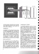
Figure
1. Rear
Panel
Connection Facilities and Adjustments
PLAY
The
pairs of TAPE IN jacks serve
two
purposes;
1. With
the
selector switch in
"TAPE"
posi-
tion, signals can be played from a
tape
recorder
set
for playback mode of operation.
This permits playing
the
tape
source stereo-
phonically or monophonically (determined
by position of MONO IN pushswitch).
2. With
the
selector switch in
any
other
posi-
tion,
and
while
your
tape
recorder is
recording, you can
monitor
the
resulting
tape
quality
by depressing
the
MONITOR
(TAPE) pushswitch. This presumes
that
your
recorder is
equipped
with separate
record and playback heads and separate
record and playback electronics.
RECORD 1
& 2
Connecting these jacks
to
the
line or
"radio
"
inputs of a
tape
recorder permits recording from
the
program source indicated by
the
selector
switch.
The
signals available
at
this pair of jacks
are
not
affected by
the
balance, volume, treble,
mid, bass, LOW
FILTER,
Hi
FILTER,
LOUD·
NESS, MONO IN (L, R)
and
Hi BLEND push-
switches on
the
front
panel.
AUXILIARY
High level AUX
input
jacks are
for
miscellaneous
sources such as
extra
tape
players
with
self-
2