
Instruction manual

dard
zipcord
will reveal some
form
of
coding
on
the
insulation, e.g., ridge
or
groove on
one
edge,
one
of
the
wires
may
be "silver" while
the
other
is bare
copper
.)
Coded
wires help insure
identical
connections
for each channel.
For
each channel,
the
coded
wire can be
connected
between
the
"common"
terminal
of
your
loud -
speaker and
the
GROUD terminal
of
the
ampli -
fier channel.
The
remaining
uncoded
wire is
then
connected
between
the
remaining loudspeaker
and amplifier terminals. This insures
correct
pola-
rity or phasing of identical loudspeakers.
If
there
is
any
doubt
about
phasing of loudspeaker
pairs,
or
if
they
are
not
identical loudspeakers,
a simple listening
test
can verify
correct
phasing.
With program signals fed to
both
channels, and
with
the
MONO IN
pushswitches
depressed,
the
sound should
appear
to
originate
at
a
point
midway between
the
loudspeakers, with
the
balance
control
centered
. As
the
balance
control
is
turned
away from
the
center
position,
the
sound
source should
appear
to
move
toward
one
of
the
loudspeakers. Room acoustics can sometimes
make this
test
ambiguous or
confus
ing. If so,
temporarily
move
the
loudspeakers as close toge-
ther
as possible.
Then
set
the
controls
for
balanced
MONO
operation
and listen
to
program material
with strong bass passages. Reverse
the
wires
to
one
of
the
loudspeakers and listen
to
the
same
passage again. If
there
is noticeably less bass with
this reversed
connection,
change
the
connections
back
to
the
original arrangement. If
there
is noti-
ceably
more
bass, leave
the
wires
connected
in
reverse.
These phasing procedures should be used with
each
stereo
pair of loudspeakers,
whether
MAIN
or REMOTE. If
both
pairs
of
loudspeakers are
used in
the
same listening area , ensure
that
the
MAIN pair is also
"in
phase" with
the
REMOTE
pair.
CAUTION :
NEVER DIRECTLY CONNECT THE LOUD-
SPEAKER
TERMINALS
OF ONE CHANNEL
IN
PARALLEL
WITH THOSE OF ANY
OTHER.
ANY RESULTING DAMAGE IS
NOT
COVERED
UNDER
WARRANTY.
FM ANTENNA
The
best FM reception is
obtained
with a Log-
Periodic
type
antenna,
mounted
on a good
quality
rotor
system.
For fringe areas, Marantz
recommends
a Log-
Periodic
antenna
with six
or
more
elements
de-
signed expressly for FM reception.
For
minimum
local noise and
multipath
pickup
by
the
lead-
in wires, use a balanced and shielded
300-ohm
cable. (An unshielded lead-in wire can
act
as
an omnidirectional
antenna,
and can cancel
the
directional benefits of
your
antenna.) Low-loss
300-ohm
shielded cable consists of
two
inner
conductors
plus an
outer
shield
and
insulating
jacket. This
type
of shielded cable effectively
prevents
the
lead-in
from
contributing
multipath
distortion.
For
rural areas, it is
recommended
that
a local
dealer be consulted
about
antenna
installation and
lightning
arrestor
protection.
Master
antenna
svs-
terns are
not
recommended
for
use
with
your
Model
2270;
such systems are usually designed
expressly
for
television reception and
frequently
suppress FM signals before
distribution.
In addition,
master
antenna
systems
often
severely limit good
quality
FM reception.
Where
outdoor
antennas
are
prohibited
or
incon-
venient, use a simple
form
of
300-ohm,
TV
"rabbit
ear"
antenna
or
the
simple
ribbon-type
folded
dipole
antenna
supplied with
the
Model 2270.
Both are practical and will give satisfactory results
in primary signal areas.
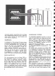
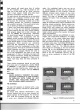
Your
Model
2270
Receiver
will
accept
either
a 75-ohm
or
300-ohm
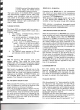
antenna.
(See diagram Figure 3.)
The
300-ohm
antenna
cable should be
connected
to
the
two
terminals
marked FM on
the
ANTENNA
terminal. When
using 75-ohm coaxial
antenna
cable,
connect
its
shield
to
the
"G"
(GROUND) terminal, and its
inner or
center
conductor
to
either
of
the
FM
terminals.
AM
ANT
tNN
A
FM
ANf[
NNA
...
NT2,N".
...
"'''''
1.''''1'01'''
,
l1li
Ill M 0 r M
.
...
O,.;~"';'
:-
•
I <i I,
"
o e
llIJi
iiil
e
.
.
~
.
..
, ,
I •
:
I
'
,
, .
lOOO UNSHIELDED
~
.
~ ~
TRAN. SM tSSK)N LI NE •
WIRE
(TW IN l EAD ' : !
SIN GLE:
fM
AN
TE
m".
rM ANT£ N NA
AVO
. ,,"TC""""'"
A....
"'''''T
e:''''
~A
I 0
"
!J
;
~
oori
""
lIlIii
"iil
...
. .I. e
.
~.
i3B88
.
, I I , I
: . :
,
,
,
,
. . .
•
. . •
SHIELD
750
COAX.
~
soon SHI[ l OEO
TRANSMISSiON . ..SHIELD
TRAN
SMI
SSION LI NE
LINE
~
Figure
3.
FM/AM
Antenna
Connection
4