
Instruction manual
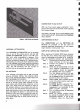

Figure
4.
AM
Ferrite-rod
Antenna
ANTENNA ATTENUATOR
The
ANTENNA ATTENUATOR can be switched
into or
out
of
the
antenna
circuit. Use
the
AN-
TENNA ATTENUATOR switch in
the
"IN"
posi-
tion
only when overloading is
apparent
from
reception of
one
station
at
several
points
of
the
dial and is affecting reception of a desired station.
Overloading may also cause severe
distortion
which
will
not
disappear with proper
antenna
orientation.
(Note: With
the
ANTENNA ATTENUATORswitch
"IN,"
the
FM sensitivity and
the
number of
stations
that
can be received are reduced.)
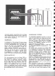
AM ANTENNA
Your
Receiver is equipped with an AM ferrite-rod
antenna. BEFORE USING THE MODEL
2270,
PULL THE ANTENNA AWAY FROM REAR PA-
NEL AS SHOWN IN FIGURE
4.
The
ferrite-rod
antenna
will give you satisfactory
results
to
primary signal areas. However, an
out
-
door
antenna
will provide
better
reception in rural
areas. Two single wires are required
to
make an
AM
outdoor
antenna. First,
connect
one
end
of
a
single wire
to
the
AM
antenna
terminal on
the
rear
panel, and
the
other
end
at
a very high position out-
doors
(the
higher
the
better,) or swing it from
the
window of
your
room. Next,
connect
the
other
sin-
gle wire between
the
"G"
(GROUND) terminal of
your
Model
2270
and an earth ground (such as a
water pipe.)
CONNECTION TO AC OUTLET
With
the
front
panel
power
pushswitch
"out,"
plug
the
line cord into an electrical
outlet
supplying
the
proper
voltage.
CAUTION: DO NOT PLUG YOUR MODEL 2270
INTO A
DCOUTLET
SINCE SERIOUS DAMAGE
WILL OCCUR.
CONVENIENCE OUTLET
One UNSWITCHED and
one
SWITCHED AC
OUTLET are provided on
the
rear panel for
powering associated
components
of
your
system
(tape recorder, record player, etc.).
SIMPLIFIED OPERATING PROCEDURE
When operating
the
Model
2270
Stereo Receiver
for
the
first time, follow these simple directions.
Later, full advantage can be taken of its versatility
with
the
remaining controls and pushswitches.
Step 1.
Connect
the
FM
antenna
to
the
appro-
priate terminals on
the
rear panel.
Step
2.
Connect
the
speakers
to
the
MAIN
speaker terminals.
Step 3. Check
that
all pushswitches are in
the
"out"
position. Pushswitches in
the
"in"
position should be depressed
for releasing
to
the
"out"
position.
Step 4.
Turn
the
volume control all
the
way
to
the
left (counter clockwise) and
set
the
balance control in mid-position
(pointer
to
dot
at
12 o'clock).
Step
5.
Rotate
treble, mid, and bass controls
to
the
12
o'clock
position (each pair
of pointers
to
dot).
Step
6.
Set
MAIN Speaker pushswitch
"in,"
and
REMOTE
"out"
(assuming
your
loudspeakers are connected
to
the
MAIN amplifier terminals) .
Step
7.
Turn
on system power by depressing
the
power switch.
Step
8. Select
the
desired program source
by setting
the
selector switch to
the
appropriate
position. If FM or AM
is selected,
rotate
the
Gyro-Touch
5