Model PM-15S1 User Guide Integrated Amplifier
CAUTION RISK OF ELECTRIC SHOCK DO NOT OPEN CAUTION: TO REDUCE THE RISK OF ELECTRIC SHOCK, DO NOT REMOVE COVER (OR BACK) NO USER-SERVICEABLE PARTS INSIDE REFER SERVICING TO QUALIFIED SERVICE PERSONNEL The lightning flash with arrowhead symbol, within an equilateral triangle, is intended to alert the user to the presence of uninsulated “dangerous voltage” within the product’s enclosure that may be of sufficient magnitude to constitute a risk of electric shock to persons.
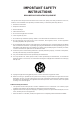
IMPORTANT SAFETY INSTRUCTIONS READ BEFORE OPERATING EQUIPMENT This product was designed and manufactured to meet strict quality and safety standards. There are, however, some installation and operation precautions which you should be particularly aware of. 1. Read these instructions. 2. Keep these instructions. 3. Heed all warnings. 4. Follow all instructions. 5. Do not use this apparatus near water. 6. Clean only with dry cloth. 7. Do not block any ventilation openings.
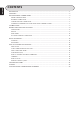
ENGLISH CONTENTS BEFORE USE ........................................................................................................................................ 1 FEATURES ............................................................................................................................................ 2 BEFORE MAKING CONNECTIONS ..................................................................................................... 3 WIRING SPEAKER CABLE .........................................
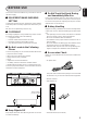
ENGLISH BEFORE USE This section must be read before any connection is made to the mains supply. 7 Do Not Touch Hot Spots During and Immediately After Use 7 EQUIPMENT MAINS WORKING SETTING During and immediately after use, the PM-15S1 is hot in areas other than the controls and rear panel connection jacks. Do not touch hot spots and especially the top panel. Contact with hot areas can cause burns.
ENGLISH FEATURES Marantz has surpassed itself with the new PM-15S1 stereo integrated amplifier, which incorporates many of the design concepts of the PM-11S1 flagship model amplifier. Power • Power Transformers As in the PM-11S1 model, the PM-15S1 also incorporates the HDAMSA2 as the main amp module. The HDAMSA2 includes an input buffer, linear control volume and power buffer.
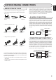
WIRING SPEAKER CABLE • Be careful not to short circuit in wiring speaker cables. • Peel off the corting of speaker cable as shown below. Approx. 1 cm Cut the corting of cable. Peel off the edge of cable. Twist conductors. Insert conductor of cable. BI-WIRING CONNECTION A bi-wiring connection separately connects the low and mid/ high jacks of the speaker to the amplifier using separate speaker cables.
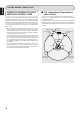
ENGLISH BEFORE MAKING CONNECTIONS SPEAKER POSITIONING FOR SUPER AUDIO MULTI-CHANNEL SOUND In order to enjoy Super Audio CD multi-channel sound with the best possible acoustics, it is recommended to position speakers as specified in ITU-R BS.775-1 of the International Telecommunication Union (ITU). Super Audio CD multi-channel discs are recorded and mixed so as to achieve the optimum effect with a speaker system laid out as specified in ITUR BS.775-1.
CONNECTIONS Connection Example 1: Basic Connection for Normal Stereo Playback • Use a bi-wiring connection (pg. 3) for speakers. Refer also to the instruction manuals of components to connect equipment correctly. • Set the SPEAKER button on the front panel in the ON position. • To record, set the REC OUT button on the front panel in the ON position.
CONNECTIONS Connection Example 2: Basic Connection for 5.1 Multi-Channel Playback Using 3 PM-15S1 The three PM-15S1s are connected by FCBS. For the FCBS connection, prepare 3 portable audio connection cables with monaural ⇔ monaural miniplugs or stereo ⇔ stereo miniplugs as described “ABOUT FCBS” on pg. 16. Set the ID numbers for the PM15S1 units as explained “HOW TO SET ID” on pg. 19. When the PM-15S1 of ID 1 is operated, those of ID 2 and ID 3 will operate in sync.
Connection Example 3: Complete Bi-Amp Connection for Stereo Playback Using 2 PM-15S1 The speaker system must support a bi-amp connection, therefore to determine whether your speakers do or not, check in the instruction manual that came with your speakers or contact the manufacturer. The two PM-15S1s are connected by FCBS. For the FCBS connection, prepare 2 portable audio connection cables with monaural ⇔ monaural miniplugs or stereo ⇔ stereo miniplugs as described “ABOUT FCBS” on pg. 16.
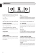
ENGLISH NAMES AND FUNCTIONS OF PARTS FRONT PANEL q POWER ON/OFF Switch This switch turns power to the PM-15S1 ON and OFF. When pressed, power is activated and the blue indicator on the display w lights up. Approximately 8 seconds after power is activated, audio output is enabled. Pressing the switch again turns power OFF. w Display The display displays the selected input source, volume level and setting status.
!2 REC OUT Button This button turns the signals output from the RECORDER 1 and 2 OUT jacks on the rear panel ON and OFF. When output is ON, the center of the button is lit a blue color. For instructions on how to record, see “RECORDING” on pg. 15. When RECORDER 1 is selected as the input source, signals are not output to the RECORDER 1 OUT jack. The same goes for the RECORDER 2 OUT jack when RECORDER 2 is selected as the input source.
ENGLISH NAMES AND FUNCTIONS OF PARTS REAR PANEL A PHONO GND Terminal Connect the grounding wire from an analog record player here. B PHONO Input Jacks These jacks are for connecting to an analog record player. Both MC and MM cartridges can be used, therefore set the PHONO MC button on the front panel according to the type of cartridge you are using. In the bi-amp mode, the R channel jack cannot be used.
ENGLISH NAMES AND FUNCTIONS OF PARTS J Operating Mode Switch This switch is for setting the operating mode of the PM15S1. STEREO: Set to use the PM-15S1 as an ordinary 2-channel stereo amplifier. BI-AMP: Set to use two PM-15S1s in a complete bi-amp connection with FCBS. For more information on the biamp mode, see “ABOUT THE BI-AMP MODE” on pg. 16. K F.C.B.S. IN/OUT Jacks You can connect and synchronize up to four PM-15S1s in a complete bi-amp connection or multi-channel connection.
ENGLISH NAMES AND FUNCTIONS OF PARTS REMOTE CONTROLLER This remote controller can control the PM-15S1 and Marantz Super Audio CD players and DVD players that have a remote control receptor. The operations possible by remote control may differ with each component, therefore see the instruction manual that came with the component. Remote controller buttons are laid out as shown below. OPEN/ CLOSE z Input Selector Buttons These buttons are for selecting the input source to use in playback.
The buttons in groups , and . are for operating Marantz products other than the PM-15S1, such as Super Audio CD players and DVD players. The function of each button changes to match the component selected as the input source from the input selector buttons z. When the CD button is pressed, the buttons in groups , and . function as indicated in the table below. These buttons can be used only when a Marantz Super Audio CD player is connected to the CD input jacks.
ENGLISH BASIC OPERATION PLAYBACK To explain how to play back input sources, representative examples are given with an Super Audio CD player and analog record player. Before starting either procedure, check the component is correctly connected to the PM-15S1. 7 Disc Playback on an Super Audio CD Player 1. Press the power ON/OFF switch of the Super Audio CD player to activate power to it. 5. Set a record on the analog record player and play it. 6. Adjust the volume level from the VOLUME knob r on the 7.
ENGLISH BASIC OPERATION RECORDING This example explains how to record from an input source such as an Super Audio CD player to a recording device such as a CD-R. 1. Press the power ON/OFF switch of the Super Audio CD player and CD-R to activate power to both components. 2. Press the POWER ON/OFF switch q of the PM-15S1 to 3. 4. 5. 6. 7. activate power to it. Approximately 8 seconds after power has been activated, the muting turns OFF and audio output is enabled.
ENGLISH HOW TO USE AND SET FEATURES ABOUT FCBS FCBS is short for Floating Control Bus System. It is a communication system that connects up to four PM-15S1s over a dedicated bus line so as to enable synchronized operations amongst them via 2-way data communications. The FCBS connections can be made with either of the below two types of portable audio connection cable. Prepare the number of connection cables for the number of PM-15S1s to connect.
2. Set the attenuation level. The setting changes with each ATTENUATION (ATT.) press of the ATT button on the PM-15S1. Attenuation is a one-touch feature for reducing volume level. When the ATT button on either the PM-15S1 or the remote controller is pressed, the volume level is attenuated. When the PM-15S1 is shipped from the factory, the attenuation level is set to –20 dB, but it can be set to –20 dB, –40 dB or –∞. 1.
ENGLISH HOW TO USE AND SET FEATURES TRIMMING Trimming is a feature for adjusting left and right volume balance. Trimming is performed from the remote controller. TRIM : This button starts trimming. When multiple PM15S1s are connected, this button selects the amplifier with which to perform trimming. In such case, trimming is performed in the order of the lowest to highest ID number. EXIT : This button ends trimming. 3 : This button increases the trimming level.
ENGLISH HOW TO USE AND SET FEATURES HOW TO SET ID INPUT SELECTOR knob DISPLAY button If using the PM-15S1 by itself as a stereo amplifier, set the ID to “0”. When the PM-15S1 is shipped from the factory, the ID is set to “0”. When the ID is set to a number other than “0”, the PM15S1 cannot be used for standalone operation. The ID number of the PM-15S1 appears on the display for about 3 seconds after power is activated.
ENGLISH HOW TO USE AND SET FEATURES REMOTE CONTROL JACKS The REMOTE CONTROL jacks are for connecting components that are capable of remote control (D.BUS jacks) such as a Marantz Super Audio CD Player or DVD Player. This enables these other components to be operated with the remote controller included with the PM-15S1. The PM-15S1 comes with an RC-11PMS1 system remote controller that can operate the basic features of Marantz Super Audio CD Players and DVD Players.
If you experience trouble with the PM-15S1, make the below checks before thinking the worst. Improper operation can cause the PM-15S1 to behave in a way that makes you think something is wrong with the equipment when actually not. If the trouble cannot be fixed after making the below checks, contact the place of purchase, your nearest Marantz dealer, our customer service center or our repair service center. * Power does not turn ON. 1.
ENGLISH TROUBLESHOOTING 7 Error Messages When multiple PM-15S1s are connected by FCBS, the below error messages may appear on the display. In these cases, there is a problem with the ID number setting or remote cable connection. Check the ID numbers and remote cable as indicated in the below table. For details on how to set ID numbers, see “How to Set ID” on pg. 19. Error message Meaning What to do 1 ERROR 02 ID 2 is used with more than one amp. 2 ERROR 03 ID 3 is used with more than one amp.
Tone control Bass (50Hz) ........................................................... ±10dB Treble (20kHz) ....................................................... ±10dB Power requirement ......................................... AC 120V 60Hz Power consumption (UL6500) ................................................................ 230W (4Ω, 120W x 2 output) ............................................ 460W Accessories Remote controller ..........................................................
Printed in Japan SC-11S1_UN_cover etc.indd 2 09/2008 00M22AJ851310 mzh-g 07.9.