INSTALLING & OPERATING YOUR MARCO WOOD-BURNING FIREPLACE ARCHITECT'S 41 " MASONRY FIREPLACES Patents Pending # MODEL DESCRIPTION 792870 REFERENCE A41 MTR 792871 A41 MTU ARCHITECT'S 41" MASONRY "TUDOR" 792872 A41 MC ARCHITECT'S 41" MASONRY "CUSTOM" ARCHITECT'S 41" MASONRY "TRADITIONAL" CHECK LOCAL CODES PRIOR TO INSTALLATION OPTIONAL FEATURES: GLASS DOORS OUTSIDE AIR KIT THlS MANUAL PROVIDES ALL THE INSTRUCTIONS NECESSARY FOR THE BUILDER OR HOMEOWNER TO INSTALL THE ARCHITECTS 41" MASONRY FIREP
TABLE OF CONTENTS I . ACCESSORIES . . . . . . . . . . . . . . . . . . . . . . . . . . . . . . . . . . . . . . . . . . . . . . . . . Page 1 11. INSTALLATION INSTRUCTIONS Introduction . . . . . . . . . . . . . . . . . . . . . . . . . . . . . . . . . . . . . . . . . . . . . . . . . . . . . . . . Page 1 Selecting Your Fireplace Location ..................................... Page Clearances ......................................................... Fireplace Overall Dimensions ...................................
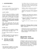
This MARCO fireplace and components are safe when installed according to this Installation Manual. Unless you use MARCO components which have been designed and tested for the fireplace system, you may cause a fire hazard. 1. ACCESSORIES FIREPLACE GRATE: MARCO 41" Masonry fireplaces may be installed in a conventional home or a prefabricated home. This unit has been equipped with a grate designed lo keep the operation of your fireplace efficienl and safe. See Page 17 for operating instructions.
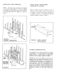
Do not place the fireplace on soft-surfaced floor covering such as carpeting. The mounting surface must be flat and hard (such as plywood, wood flooring, particle board or any other hard-surfaced material), and evenly support the total base of the fireplace. A raised platform may be used to support the fireplaces. LOCATION Corners shoutd be considered where space is limited or at a premium. A corner-installedfireplace can make use of space that may not normally be used (see Figure 1).
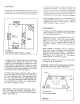
BLACK PORTION OF FRAME NOT TO BE COVERED WITH COMBUSTIBLE MATERIALS FIGURE 3 C / 2" MIN. FRAMING INSTRUCTIONS If framing around the fireplace is designed to incorporate book shelves, wood bins, closets, etc.. these should not project beyond the safety zone (Figure 3). U* NOTE: SEE RGURE 5 FOR fRONT VIEW OF FRAMING.
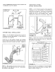
INSTALLING YOUR FIREPLACE METAL SAFETY STRIP-OFFSET (SUPPLIED BY OTHERS) STEP 1 : Frame the cavity of opening for the fireplace at the chosen location (Figure 6). Move the fireplace into position and install false header and metal safety strips (provided) under the fireplace as shown in Figure 7. When the fireplace and hearth extension are not installed at the same height a custom safety strip will be required. The safely strip shall be constructed of a minimum thickness of .
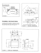
NOTE: COMBUSTION AIR INLET DUCTS MUST NOT TERMINATE IN AlTlC SPACE. COMBUSTION AIR INTAKE STEP 1 : A 4-112" diameter opening will be required for installation of the air inlet assembly. Cut hole where no obstructions are expected, Install the air inlet assembly through floor opening. Secure assembly to floor. Slip flexible duct onto air inlet assembly collar. Secure flexible duct to collar with a hose clamp. (Figure 10).
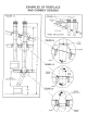
EXAMPLES OF FIREPLACE AND CHIMNEY DESIGNS .
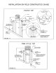
INSTALLATION ON FIELD CONSTRUCTED CHASE ROUND TOP CHASE TOP 36- MiHIMUM OR 2 FEET ABOVE HIGMESf METAL SPACERS(4) OR EQUIVALENT 2 I4 FRAMING CONTINUOUS SPACER MADE FROM NOH-COMBUSTIBLE MATERIAL WllW Kz.
INSTRUCTIONS FOR OFFSET OF CHIMNEY USlNG ELBOWS TO INSTALL ELBOWS 1 . To achieve desired offset, you may install combinations of 12", 18", 36"+ lengths of double wall pipe (see single offset chati and Figure 20A). 2. Chimney weight above offset resls on return elbow. Straps must be securely nailed to rafters or joists. (See Figure 20B). 3. Maximum length of pipe between supports (return elbow or chimney pipe support) is 6' of angled run. Maximum of two 6' angled run sections per chimney system.
INSTALLING YOUR DOUBLE-WALL CHIMNEY SYSTEM BEFORE YOU BEGIN INSTALLING YOUR DOUBLE WALL CHIMNEY SYSTEM DETERMINE HOW MUCH PtPE AND ACCESSORIES YOU WILL NEED. SEE PAGE 6 FOR EXAMPLES O f CHIMNEY AND TERMINATION DESIGNS. Each double-wall chimney section consists of an outer pipe, flue pipe and single-piece wire spacer. The pipe sections are not unitized and must be assembled independently as the chimney is installed. (Figure 21).
CHIMNEY PIPE SUPPORT The chimney pipe support is a double-wall, unitized 12" length of pipe and is designed to relieve the extra weight toad on the fireplace and elbows when high chimneys are installed. A CHIMNEY SUPPORT IS REQUIRED AFTER A STRAIGHT CHIMNEY RUN OF 35 FEET ABOVE FIREPLACE OF RETURN ELBOW. (Figure 24). 1B:tpE FIGURE 24 STEP 3: tf you are remodeling, cover exposed pipe and cut a 20" hole on ceiling directly a b v e center of chimney pipe (Use Plumb Bob).
STEP 5: After cutting the hole in the roof, uncover the pipe and add sections unlil the chimney extends a minimum of 14 inches above the highest point of the roof cutout. (Figure 27). STEP 8: Place flashing into position on unshingled root. Hold in position by nailing shingles in place over the flashing edges. STEP 9: Install storm collar on the chimney and push down near the top of the Ilashing. Apply waterproof caulking around the top of the storm collar. (Figure 29).
INSTALLING THE GAS LINE IMPORTANT: Install the gas line before finishing the fireplace. If desired, a decorative gas appliance may be installed. Use only iron pipe, 112" size, and appropriate fittings. When installing gas line, a valve designed for installation outside the fireplace is required (Figure 31). STEP 5 : Seal hole around gas line on refractory wall with cement or any other non-combustible material. (Figure 33).
TEST FOR GAS LEAKS 1 All gas piping and connections must be tested for leaks after the installation is completed. Be sure gas valve is turned on. Apply soap suds solution to all connections and joints. If bubbles appear, leaks can be detected and corrected. 00 NOT use a match or open flame of any kind to test for leaks. Never operate any appliance with leaky connections.
HEARTH EXTENSION: If there is a combustible floor construction in front of the fireplace, a heaRh extension is required to prolect it. The hearth extension, as shown in Figure 35,must be a minimum of 20" deep by 65" wide and extend a minimum of 12" beyond each side of the fireplace opening. EXAMPLE OF DETERMING HEARTH EXTENSION EQUIVALENT To determine the thickness required for any material: K new material x 1" = Thickness Required .84 Example for Insulating Board-K-FAG 19 (K trom Figure 36).
IV. OPERATfNG INSTRUCTIONS DAMPER CONTROL LEVER FIREPLACE GRATE: The damper control lever located inside the lop front of the firebox has been engineered lo provide safe operation of your fireplace. Do not close the damper in an attempt to reduce a large fire. To do so may cause a potential smoke hazard, just as any fuel-burning appliance would do ifnot properly exhausted.
MANTLES 1 FIREPLACE AND HEARTH EXTENSION ON COMBUSTIBLE F LDOR i FINISHED WALL - FALSE HEADER COMBUSTIBLE O P n O H U NOM-COMBUS DECORATIVE CWERIAG COUBVSTlSLE FLOOR COVERIHC / NON-COMBUSTIBLE _/ DECORATIVE FACING (DO NOT OVERLAP THE OPENING) STEEL METAL SAFETY FlG U RE 38 H U R M EXTEHSIOH OR EOUIVALEUT I If a raised headh is constructed, the hearth must be buitt out of completely noncombustible materials.
Read operation a n d warranty manuals thoroughly before installing and using this fireplace. DO'S AND DON'TS This Fireplace is intended for use with solid wood fuel only. c Keep base of fireplace clean of excess ash accumulation to prevent grate "burnout'. When installing this fireplace in cold climate areas be sure to follow the cold climate installation instruclions outtined in !his booklet. Keep the fire screen closed at all times when burning, except when adding fuel.
THIS FIREPLACE IS NOT INTENDED TO BE . ' USED WITH ANY COMPONENTS OTHER THAN THOSE SPECIFIED IN THIS MANUAL COMPONENT PARTS U.L.
hA,M d P C ! MARC0 ME., INC. ,-,.m I-.. ......A,-. I -.A e. -..* .. .-,.. ..-. r .