® ACM100 Alternating Current Monitor User’s Manual Revision 1.2 Copyright © 2012 Maretron, LLP All Rights Reserved Maretron, LLP 9014 N. 23rd Ave #10 Phoenix, AZ 85021-7850 http://www.maretron.com Maretron Manual Part #: M001701 Revision 1.
ACM100 User’s Manual Revision History Revision Description 1.0 Original document 1.1 Corrected AC sensor part number Updated mounting drawing 1.2 Added sensed voltage and current range specifications Added prohibition of red Loctite threadlocking compound and cleaning agents containing acetone Page ii Revision 1.
® Table of Contents 1 Introduction ...........................................................................................................................1 1.1 Firmware Revision .................................................................................................... 1 1.2 ACM100 Features .................................................................................................... 1 1.3 Quick Install .....................................................................................
ACM100 User’s Manual Figure 4 – Single-Phase (Dual Line) Connection Diagram ........................................................ 6 Figure 5 – Three-Phase Connection Diagram ........................................................................... 8 Figure 6 – Mounting Surface Template ................................................................................... 17 Table of Appendices Appendix A – NMEA 2000® Interfacing.............................................................................
® 1 Introduction Congratulations on your purchase of the Maretron Alternating Current (AC) Monitor (ACM100). Maretron has designed and built your ACM100 to the highest standards for years of dependable and accurate service. Maretron’s ACM100 is a device which monitors AC power sources and outputs information about these sources onto the industry standard NMEA 2000® marine data network.
ACM100 User’s Manual o 230VAC single phase o 380VAC Y Three-phase (380Y) 1.3 Quick Install Installing the Maretron ACM100 involves the following five steps. Please refer to the individual sections for additional details. 1. 2. 3. 4. 5. Unpack the box (Section 2.1) Choose a mounting location (Section 2.2) Mount the ACM100 (Section 2.3) Connect the ACM100 (Section 0) Configure the ACM100 (Section 2.5) 2 Installation 2.
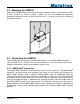
® 2.3 Mounting the ACM100 Attach the ACM100 securely to the vessel using the included stainless steel mounting screws or other fasteners as shown in Figure 1 below. Do not use threadlocking compounds containing methacrylate ester, such as Loctite Red (271), as they will cause stress cracking of the plastic enclosure. Figure 1 – Mounting the ACM100 2.4 Connecting the ACM100 The ACM100 requires two types of electrical connections: 1) the NMEA 2000® connection (refer to Section 2.4.
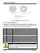
ACM100 User’s Manual Figure 2 – NMEA 2000® Connector Face Views 2.4.2 AC Sensor Connections The ACM100 sensor connections are made by connecting to the 12-pin terminal strip on the top of the unit. First, remove the four screws at the corners of the unit detaching the splash guard from the unit. On the bottom of the splash guard, you will find a label detailing the wire connection to pin number assignments, which are repeated in the table below.
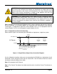
® WARNING: If the supplied current transformer is placed around a wire carrying AC current, then extremely high voltages can develop on the output leads of the current transformer, with severe risk of electrocution. For safety, keep the output leads of the current transformer(s) shorted or tied together until they are connected to the proper terminals on the ACM100.
ACM100 User’s Manual a. Connect the black wire to pin 7 (IA+) on the ACM100 b. Connect the white wire to pin 8 (IA-) on the ACM100 c. Disconnect the hot wire from the AC power source and place it through the hole in the Current Sensor such that the arrow on the Current Sensor points towards the AC power source. Then, reattach the hot wire to the AC source. Step 3: You must supply a cable for connecting the voltage sense pins on the ACM100 to the AC source.
® will need to purchase an optional current sensor (Part # M000630) for monitoring this type of system. Step 1: De-energize the AC Source. Step 2: The Current Transformer has black and white wires. Install the Phase A Current Transformer as follows: a. Connect the black wire to pin 7 (IA+) on the ACM100 b. Connect the white wire to pin 8 (IA-) on the ACM100 c.
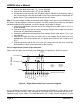
ACM100 User’s Manual 2.4.2.3 Three-Phase (Phase A, B, C) Connection Please refer to Figure 5 for connecting the ACM100 to a three phase system. Current Transducer Fuse Line (Phase C) Current Transducer Fuse Current Transducer Line (Phase A) Fuse AC Source Line (Phase B) Neutral + + U.S.
® c. Disconnect the Phase B hot wire from the AC power source and place it through the hole in the Current Sensor such that the arrow on the Current Sensor points towards the AC power source. Then, reattach the Phase B hot wire to the AC power source. Step 4: Install the third Current Transformer as follows: a. Connect the black wire to pin 11 (IC+) on the ACM100 b. Connect the white wire to pin 12 (IC-) on the ACM100 c.
ACM100 User’s Manual c. Connect the black wire from one end of the second Voltage Sense cable to pin 3 (VCLine) on the ACM100 d. Connect the black wire from the other end of the second Voltage Sense cable to a fuse appropriately sized for the black wire (18 gauge wire minimum and 3 amp fuse or less). e. Connect the other end of the fuse to the AC source hot wire (the fuse should be placed within 6 inches of the connection to the hot wire). 2.4.
® 2.5.3 AC Circuit Type You must configure the ACM100 as to what type of AC circuit connection it is monitoring. The allowable values for this parameter are as follows: • • • Single-Phase (Phase A) – use this value when power is connected via a single hot wire and a single neutral wire (a typical 110VAC connection in the US).
ACM100 User’s Manual reconnecting the current transformer, you may change the value of this parameter from the default value of “Normal Install” to “Inverse Install” to correct for this. 2.5.5.5 Current Transformer B If you notice that the current of phase B is negative when it should be positive, or vice-versa, then the current transformer has been installed backwards.
® 3.1 Line-Specific and Line-to-Neutral Measurements AC Source Type Available Data Parameter Bus Generator Utility Average Phase A Phase B Phase C Line-Neutral AC 9 9 9 9 9 91 RMS Voltage 9 9 9 9 AC RMS Current 91 9 9 9 9 9 AC Frequency 91 9 9 9 9 Real Power 91 9 9 9 9 Apparent Power 91 9 9 9 9 Reactive Power 91 9 9 9 9 Power Factor 91 Total kW Hours 9 9 9 Export Total kW Hours 9 9 9 Import Notes: 1.
ACM100 User’s Manual • • • • Clean the unit with a soft cloth. Do not use chemical cleaners as they may remove paint or markings or may corrode the ACM100 enclosure or seals. Do not use any cleaners containing acetone, as they will deteriorate the plastic enclosure. Ensure that the unit is mounted securely and cannot be moved relative to the mounting surface. If the unit is loose, tighten the mounting screws. Check the security of the cable connected to the NMEA 2000® connector, and tighten if necessary.
® 6 Technical Specifications As Maretron is constantly improving its products, all specifications are subject to change without notice. Maretron products are designed to be accurate and reliable; however, they should be used only as aids to navigation and not as a replacement for traditional navigation aids and techniques.
ACM100 User’s Manual Electrical Parameter Sensed Voltage Sensed Current Operating Voltage Power Consumption Load Equivalence Number (LEN) Reverse Battery Protection Load Dump Protection Value 0-240 VAC 0-200 A 5 to 36 Volts 100 mA 2 Yes Yes Comment 120,120/240,240,208Y,380Y configurations With supplied current transformer DC Voltage NMEA 2000® Interface NMEA 2000® Spec. (1LEN = 50 mA) Indefinitely Energy Rated per SAE J1113 Mechanical Parameter Value Comment 3.50” x 4.20” x 2.
® 8 Installation Template Please check the dimensions before using the following diagram as a template for drilling the mounting holes because the printing process may have distorted the dimensions. Figure 6 – Mounting Surface Template Revision 1.
ACM100 User’s Manual 9 Maretron (2 Year) Limited Warranty Maretron warrants the ACM100 to be free from defects in materials and workmanship for two (2) years from the date of original purchase. If within the applicable period any such products shall be proved to Maretron’s satisfaction to fail to meet the above limited warranty, such products shall be repaired or replaced at Maretron’s option.
® Appendix A – NMEA 2000® Interfacing ACM100 NMEA 2000® Periodic Data Transmitted PGNs PGN 65001 – Bus #1 Phase C Basic AC Quantities PGN 65002 – Bus #1 Phase B Basic AC Quantities PGN 65003 – Bus #1 Phase A Basic AC Quantities PGN 65004 – Bus #1 Average Basic AC Quantities PGN 65008 – Utility Phase C Basic AC Quantities PGN 65011 – Utility Phase B Basic AC Quantities PGN 65014 – Utility Phase A Basic AC Quantities PGN 65017 – Utility Average Basic AC Quantities PGN 65021 – Generator Phase C Basic AC Quant
ACM100 User’s Manual PGN 65005 – Utility Total AC Energy PGN 65018 – Generator Total AC Energy The ACM100 uses this PGN to transmit the total energy delivered by the power source. Field 1: Total kWh Hours Export – This field indicates the total energy delivered by the AC power source in units of 1 kWh. 2: Total kWh Hours Import – This field indicates the total energy delivered to the AC power source in units of 1 kWh.