
Computer Monitor User Manual

ACM100 User’s Manual
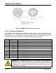
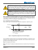
Figure 2 – NMEA 2000
®
Connector Face Views
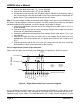
2.4.2 AC Sensor Connections
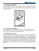
The ACM100 sensor connections are made by connecting to the 12-pin terminal strip on the
top of the unit. First, remove the four screws at the corners of the unit detaching the splash
guard from the unit. On the bottom of the splash guard, you will find a label detailing the wire
connection to pin number assignments, which are repeated in the table below.
Pin # Signal Name Connection
1
V
A
Line
Voltage Phase A Line
2
V
B
Line
Voltage Phase B Line
3
V
C
Line
Voltage Phase C Line
4
V
A
Neutral
Voltage Phase A Neutral
5
V
B
Neutral
Voltage Phase B Neutral
6
V
C
Neutral
Voltage Phase C Neutral
7
I
A+
Current Phase A Plus
8
I
A-
Current Phase A Minus
9
I
B+
Current Phase B Plus
10
I
B-
Current Phase B Minus
11
I
C+
Current Phase C Plus
12
I
C-
Current Phase C Minus
WARNING: The voltages present on AC circuits can cause electrocution.
Before making any electrical connections to the ACM100, ensure that power is
removed from all AC circuits that will be connected to the ACM100. Only restore
AC power after all connections have been made to the ACM100 and the splash
guard has been re-installed.
Page 4 Revision 1.2