® RIM100 Run Indicator Module User’s Manual Revision 1.0 Copyright © 2008 Maretron, LLP All Rights Reserved Maretron, LLP 9014 N. 23rd Ave #10 Phoenix, AZ 85021-7850 http://www.maretron.com Maretron Manual Part #: M002001 Revision 1.
RIM100 User's Manual Revision History Revision 1.0 Original document Page ii Description Revision 1.
® Table of Contents 1 Introduction ...........................................................................................................................1 1.1 Firmware Revision .................................................................................................... 1 1.2 RIM100 Features ...................................................................................................... 1 1.3 Quick Install ...................................................................................
® 1 Introduction Congratulations on your purchase of the Maretron Run Indicator Module (RIM100). Maretron has designed and built your RIM100 to the highest standards for years of dependable and accurate service. Maretron’s RIM100 monitors both AC and DC electrical circuits and reports, over an NMEA 2000® network, whether or not the electrical circuit is energized and running. The RIM100 works equally as well for monitoring manually switched loads (e.g.
RIM100 User's Manual 3. Mount the RIM100 (Section 2.3) 4. Connect the RIM100 (Section 2.4) 5. Configure the RIM100 (Section 2.5) 2 Installation 2.1 Unpacking the Box When unpacking the box containing the Maretron RIM100, you should find the following items: 1 – RIM100 – Run Indicator Module 1 – Parts Bag containing 4 Stainless Steel Mounting Screws 1 – RIM100 User’s Manual 1 – Warranty Registration Card If any of these items are missing or damaged, please contact Maretron. 2.
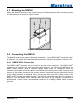
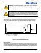
® 2.3 Mounting the RIM100 Attach the RIM100 securely to the vessel using the included stainless steel mounting screws or other fasteners as shown in Figure 1 below. Figure 1 – Mounting the RIM100 2.4 Connecting the RIM100 The RIM100 requires two types of electrical connections: 1) the NMEA 2000® connection (refer to Section 2.4.1), and 2) the monitored load connections, which are described in Section 2.4.2. 2.4.1 NMEA 2000® Connection The NMEA 2000® connector can be found on the side of the enclosure.
RIM100 User's Manual Figure 2 – NMEA 2000® Connector Face Views 2.4.2 Monitored Load Connections The RIM100 monitored load connections are made by connecting to the 12-pin terminal strip on the top of the unit. First, remove the four screws at the corners of the unit detaching the splash guard from the unit. On the bottom of the splash guard, you will find a label detailing the wire connection to pin number assignments, which are repeated in the table below.
® WARNING: The voltages present on AC circuits can cause electrocution. Before making any electrical connections to the RIM100, ensure that power is removed from all AC circuits that will be connected to the RIM100. Only restore AC power after all connections have been made to the RIM100 and the splash guard has been re-installed.
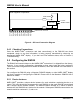
RIM100 User's Manual User-Supplied Components Power Switch Fuse Monitored DC Load + To DC - Breaker Panel Fuse RIM100 Screw Terminals 2 3 4 5 6 7 8 9 10 11 12 V1+ V1V2+ V2V3+ V3V4+ V4V5+ V5V6+ V6- 1 Figure 4 – DC Load Connection Diagram 2.4.3 Checking Connections Once the NMEA 2000® connection and load connection(s) to the RIM100 have been completed, check to see that information is being properly transmitted by observing an appropriate NMEA 2000® display.
® 2.5.2 Channel #1 - #6 Mode You must configure the RIM100 as to whether a particular channel should be enabled. The allowable values for this parameter are as follows: • • “Enable” (default) – Use this value if the channel is being used to monitor a load. “Disable” – Use this value if no load circuit is connected to the corresponding channel’s terminals. The RIM100 will indicate that no data is available for this circuit. 2.5.
RIM100 User's Manual • • Check the security of the cable connected to the NMEA 2000® connector, and tighten if necessary. Check the security of all of the load connections on the top of the unit and tighten if necessary. 4 Troubleshooting If you notice unexpected operation of the Maretron RIM100, follow the troubleshooting procedures in this section to remedy simple problems. If these steps do not solve your problem, please contact Maretron Technical Support (refer to Section 6 for contact information).
® 5 Technical Specifications As Maretron is constantly improving its products, all specifications are subject to change without notice. Maretron products are designed to be accurate and reliable; however, they should be used only as aids to navigation and not as a replacement for traditional navigation aids and techniques.
RIM100 User's Manual Environmental Parameter IEC 60945 Classification Degree of Protection Operating Temperature Storage Temperature Relative Humidity Vibration Solar Radiation Corrosion (Salt Mist) Electromagnetic Emission Electromagnetic Immunity Safety Precautions Value Exposed IP64 -25°C to 55°C -40°C to 70°C 93%RH @40° per IEC60945-8.2 2-13.2Hz @ ±1mm, 13.2-100Hz @ 7m/s2 per IEC 60945-8.7 Ultraviolet B, A, Visible, and Infrared per IEC 60945-8.
® 7 Installation Template Please check the dimensions before using the following diagram as a template for drilling the mounting holes because the printing process may have distorted the dimensions. Figure 5 – Mounting Surface Template Revision 1.
RIM100 User's Manual 8 Maretron (2 Year) Limited Warranty Maretron warrants the RIM100 to be free from defects in materials and workmanship for two (2) years from the date of original purchase. If within the applicable period any such products shall be proved to Maretron’s satisfaction to fail to meet the above limited warranty, such products shall be repaired or replaced at Maretron’s option.
® Appendix A – NMEA 2000® Interfacing RIM100 NMEA 2000® Periodic Data Transmitted PGNs PGN 127501 – Binary Switch Bank Status The RIM100 uses this PGN to transmit the state of each of the connected switch inputs Field 1: Indicator Bank Instance – This field identifies the particular switch bank to which this PGN applies. Please refer to Section 2.5.1 for instructions on how to program the value of this field.