
User Guide


RIM100 User's Manual
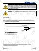
Power Switch
RIM100 Screw Terminals
Monitored
DC Load
+ To DC
- Breaker Panel
Fuse
Fuse
User-Supplied Components
1 2 5 4 3 6 7 8 9 10 11 12
V1+
V2-
V2+
V1-
V3+
V3-
V4+
V4-
V5+
V5-
V6+
V6-
Figure 4 – DC Load Connection Diagram
2.4.3 Checking Connections
Once the NMEA 2000
®
connection and load connection(s) to the RIM100 have been
completed, check to see that information is being properly transmitted by observing an
appropriate NMEA 2000
®
display. If you don’t see Run Indicator status, refer to Section 4,
“Troubleshooting”.
2.5 Configuring the RIM100
The RIM100 will transmit data over the NMEA 2000
®
network as it is shipped from the factory;
however, it may require configuration, depending on how many loads are being monitored.
There are several configurable items within the RIM100, which are detailed in the remainder of
this section.
You configure the RIM100 using a Maretron DSM250 display or other NMEA 2000
®
display
unit that is capable of configuring the RIM100. Please refer to the Maretron DSM250 User’s
Manual for details.
2.5.1 Device Instance
NMEA 2000
®
provides a unique device instance for each switch/run monitoring device on a
vessel. This value should be programmed in each RIM100 so that each RIM100 is associated
with a unique device instance number. The default instance number is 0, which is used to
indicate the first RIM100 that is hooked to the network. Subsequent RIM100s connected to the
network would be numbered 1, 2, and so on.
Page 6 Revision 1.0