N 5805 0 N 5802 0 INTEGRATED AMPLIFIER OWNER’S MANUAL
TABLE OF CONTENTS TABLE OF CONTENTS Overview 2 Installation 4 Unpacking, placement and ventilation Power requirements, Operating states 4 5 Connections 6 Rear panel overviews 6 External component connections 7 Quick Listen 11 Control 11 Front-panel overview 12 Remote control overview 13 Remote control operation 14 Browser Setup Panel 15 Setup 16 Setup navigation 16 Input setup 17 Volume setup 21 Power setup 22 Display setup 22 Advanced setup 23 SSP (surround processor integration) setup
OVERVIEW OVERVIEW INTRODUCING THE MARK LEVINSON NO5805 AND NO 5802 INTEGRATED AMPLIFIERS Congratulations on your purchase of a Mark Levinson® integrated amplifier. You now possess one of the finest audio reproduction devices in the world, a product that will provide an exceptional music listening experience for years to come. The N05805 and N05802 harness decades of superlative audio engineering and the latest advancements to deliver unmatched performance and value.
OVERVIEW N05805 Analog Input Stage The foundation of the N05805 is its proprietary PurePath circuitry- a fully discrete, direct-coupled, dual-monaural linelevel preamp circuit, for which the Shelton design team has two patents pending. A unique single gain stage mated to a digitally controlled resistor network for volume adjustment maintains maximum signal integrity and widest possible bandwidth.
INSTALLATION INSTALLATION UNPACKING PLACEMENT AND VENTILATION When unpacking your N05805 / N05802: • Install the integrated amplifier on a shelf with nothing above it, such as the top shelf in an open rack, to ensure proper ventilation. DO NOT install the integrated amplifier inside of an enclosed cabinet or rack. • Save all packing materials in case you need to ship your integrated amp in the future. • Inspect your integrated amp for signs of damage during shipment.
INSTALLATION POWER REQUIREMENTS OPERATING STATES The N05805 is configured at the factory for 100, 115, or 230 VAC power operation at 50Hz or 60Hz. Before operating the amplifier, ensure that the power label on the rear panel near the AC input connector indicates the correct operating voltage. A detachable IEC power cable intended for use in the region where the N05805 / N05802 is sold is included.
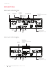
CONNECTIONS CONNECTIONS REAR-PANEL OVERVIEW NO5805 Line Out (Variable) Balanced XLR Analog In Two Single Moving Magnet and Ended RCA Moving Coil Inputs Analog In Capacitive and Resistive Loading Selection USB A for Updates IR In Ethernet Trigger In and Out RS232 DB9F Digital Inputs: • Asynchronous USB 2.0 B Audio • 2 x Optical • 1 Coax Speaker Terminals Positioned for a Variety of Connector Types REAR-PANEL OVERVIEW NO5802 Digital Inputs: • AES XLR Input • Asynchronous USB 2.
CONNECTIONS EXTERNAL COMPONENT CONNECTIONS CAUTION: Before making connections, make sure the N05805 / N05802 and all associated components are powered off and disconnected from electrical outlets. Left and right channel loudspeaker binding posts: The N 5805 / N05802 utilizes gold-plated, high-current loudspeaker binding posts. The positive binding posts, labeled + (positive), are red; the negative binding posts are black and are labeled – (negative).
CONNECTIONS Single-ended analog inputs (N05805 only): The N05805 has two analog RCA input connectors per channel (labeled S1 and S2) that accept left-channel and right-channel single-ended input signals from source components with unbalanced RCA type output connectors. Phono inputs (N05805 only): The N05805 has two analog phono preamplifier inputs per channel (labeled MM and MC) that accept left-channel and right-channel moving magnet (MM) and moving coil (MC) phono cartridge input signals.
CONNECTIONS Digital inputs (Nº5805): The N05805 has four digital audio input connectors: an asynchronous USB-B (labeled with a USB icon ), two optical (TOSLINK) S/PDIF connections (labeled T1 and T2) and one coaxial (RCA) S/PDIF connections (labeled C1).
CONNECTIONS Balanced Analog Source Component Single-Ended Analog Source Component Computer To USB Port Right Speaker 10 N05805 / N05802 INTEGRATED AMPLIFIER / OWNER’S MANUAL Digital Source Component Left Speaker
QUICK LISTEN / CONTROL QUICK LISTEN 1. Connect the supplied power cable to the N05805 / N05802’s AC Mains connector and an electrical outlet. Power on the N05805 / N05802 and all source components. 2. Press the Standby button on the N05805 / N05802’s front panel or remote control to turn it on. 3. Rotate the N05805 / N05802’s input select knob or press the Select +/– buttons on the remote to select the input for the source component you want to hear. 4.
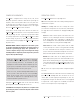
CONTROL FRONT-PANEL OVERVIEW Input/ Select Knob IR Receiver Volume/Scroll/Enter The N05805 / N05802 was designed for elegant simplicity and ergonomics. Therefore the knobs perform a variety of functions depending on the operating mode. There are two modes of operation, Listening mode and Setup mode, and three modes of standby, Green, Power-save, and Normal.
CONTROL REMOTE CONTROL REMOTE CONTROL OVERVIEW standby input volume enter menu balance mute Standby: Press this button to put the N05805/ N05802 into and out of the Standby mode. Press this button twice to wake up unit from green Standby mode. Input +/-: Press these buttons to select the desired input. Allow a moment for the relays to switch. The name and volume level of the navigate to input is indicated on the front-panel display.
CONTROL REMOTE CONTROL OPERATION Battery Installation Your N05805 / N05802 remote control comes with two AAA alkaline batteries. To install the batteries, use the included hex tool to remove the battery cover, insert the batteries and replace the battery cover and hex screw. Be sure to observe proper battery polarity. dby stan t inpu me volu u men r ente nce bala e mut Using the Remote Control When using the remote control, aim it toward the unit’s front panel IR receiver.
CONTROL BROWSER SETUP PAGE (BSP) The BSP is a highly conveient means of keeping the firmware of your amplifier up to date, for performing setup functions, and monitoring operational faults and temperature. It is accessed via a major web browser on a PC or tablet. In order to access the BSP, you must first connect the unit to your Local Area Network (LAN). If there is no easy access to a LAN there are other means of setup and control, discussed elsewhere in this manual.
SETUP SETUP SETUP MENU NAVIGATION The Setup menus on your Mark Levinson integrated amplifier allow you to customize and configure the unit for higher performance, power economy, and convenience. There are two means for accessing and navigating the Setup menu: via the front panel display using the front panel or remote control, or via the Browser Setup Page on a networked browser-enabled device. Regardless of the method you choose, the procedures are similar.
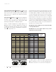
SETUP INPUT SETUP (5805) Setup Menu Input Volume Power Display Advanced Input Setup B1 [analog XLR] S1 (analog RCA) S2 (analog RCA) Phono (analog) C1 (digital coaxial) T1 (digital optical) T2 (digital optical) USB BT (Bluetooth) Set Input X Name=XXX Offset=XXX SSP=On/Off PCM Filter=XXX PLL Lock= Normal/Wide Upsample=On/Off DSD Filter= XXX BT Name BT Pairing= Enable/Forget Ph Balance= +/- 3dB Infra Filt = On/Off Phono Type= MM/MC Available for all inputs Available for analog inputs Available for digital
SETUP The following settings are available for all inputs: Name: This option offers a choice of preset names for the selected input (CD, SACD™, DVD, Blu-ray™, DAC, EQ, etc.). Additionally, the following names are available for each input: Disabled: This option removes the selected Input from the list of available inputs. The Input will be skipped when scrolling through the inputs. Browser Setup Page method: The easiest way to change input name is to select the Utility tab on the BSP.
SETUP Offset: The output level of audio devices can vary from brandto-brand and model-to-model, making some devices play louder or quieter than others. The Offset adjustment allows you precisely compensate for source volume differences so that all connected devices play at a similar volume level. The setting offers a range of –12.0dB to +12.0dB, in 0.5 dB steps.
SETUP BT Name: This displays the Bluetooth Name that will appear on your Bluetooth player device when scanning to pair. This name cannot be changed. The following setting is available only for the asynchronous USB input: DSD Filter: This setting lets you set the low-pass filter characteristic for DSD high-resolution digital content. You can select from roll-offs that begin at 47kHz, 50kHz, 60kHz or 70kHz.
SETUP VOLUME Setup Menu Input Volume Power Display Advanced Volume Max-XXX Mute=XXX Turn On=XXX Taper=XXX The Volume settings let you customize the action of the N05805 / N05802 Volume and Mute functions. Max Vol: This setting determines the maximum volume level setting in 0.5dB increments between 40.0dB and 80.0dB. The factory default maximum volume is 80.0dB. Set this value to the volume slightly below where your speakers start to distort audibly.
SETUP POWER Setup Menu Input Volume Power Display Advanced DISPLAY Power Standby = XXX Auto Off= On/Off The Power parameters let you customize power-related functions. Standby: This setting lets you set the Standby mode to one of the following options: Green: This mode removes power from almost all of the N05805 / N05802’s circuits, allowing the unit to be activated only via an IR control signal, a 5V – 12V trigger voltage or a press of the Standby button.
SETUP ADVANCED Setup Menu Input Volume Power Display Advanced Advanced Firmware Config Network Trigger Front IR The Advanced section of the Setup menu gives you access to a range of configuration and administrative settings and functions. Firmware: This menu gives you access to the following firmware-related functions: Version: Push Enter to display the version number of the currently loaded firmware.
SETUP Update: Lets you update your N05805 / N05802’s firmware, either from a drive inserted in the rear-panel USB port or via a web browser. (For browser connection guidance see Browser Setup Page (BSP) on page 25.) ENET: Select this if your N 5805 / N 5802 is connected to a home network. The unit will access the Mark Levinson server and download the latest firmware. The download and installation process takes at least 15 minutes and should not be interrupted.
SETUP Browser method: Make sure your unit is connected to a network with Internet access. Select the Home tab on the screen. Click the Software Update tab. You will be prompted for confirmation. Push OK and the unit will begin the update sequence. Please be patient and DO NOT INTERRUPT. This can take up to 15 minutes. The unit will return to Standby Mode when complete. Click Cancel to go back to the home page.
SETUP Config: This menu group allows you to lock, restore, import, or export Setup configuration settings. Config Export: Press Enter to export all setup configuration information to a thumb drive inserted in the rear panel USB port. This data can then be used to configure other N05805 / N05802 units or serve as a backup so you can quickly reconfigure your unit.
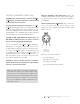
SETUP SURROUND SOUND PROCESSOR (SSP) SETUP (Applies only to the N 5805) 0 The SSP (Surround Sound Processor) mode allows the N05805 to be seamlessly integrated into a multichannel home cinema system. Any analog input may be designated as the surround sound processor input by turning this mode ON. When the SSP mode is activated the N05805’s volume control is deactivated and the level is fixed at unity gain.
SETUP SURROUND-SOUND SOURCE DEVICE Digital Output Coaxial SURROUND-SOUND PROCESSOR Composite Video Inputs 1 2 Analog Output Optical L R S-Video Inputs 3 1 2 3 Y/G 1 Component Video Inputs Pb/B HDMI Inputs 1 2 1 2 3 4 5 6 5 6 1 1 2 4 Analog Audio Outputs Right R 1 3 Y/G Pb/B 4 Y/G Pr/R Pb/B Pr/R Component Video Output Y RS-232 Pr Pb Ethernet 2 Link Analog Audio In 2 L Right Trigger Outputs IR Input R L Left 6 L L R R Subwoofer 2 Right Left AC Input
TROUBLESHOOTING TROUBLESHOOTING PROTECTION CIRCUIT FAULTS If the N05805 / N05802 encounters a potentially damaging condition, its built-in protection circuitry will shut off the amplifier, and its Front-Panel Display will show one of the error messages listed below. Follow the instructions in the Solution column to correct the condition before attempting to use the N05805 / N05802 again.
TROUBLESHOOTING NO POWER Examine the power cord to ensure that it is connected to both the AC mains connector and a working, un-switched electrical outlet. Check the mains fuse accessible on the rear panel mains outlet. Examine the electrical circuit breaker to ensure that power is being supplied to the electrical outlet to which the N05805 / N05802 is connected. Make sure the N05805 / N05802 is not in Standby mode.
TROUBLESHOOTING AUDIO HAS A HUMMING SOUND Disconnect components one at a time to isolate the problem. Once you have identified the problematic component, make sure it is properly grounded and connected to the same electrical circuit as the N05805 / N05802. VOLUME CAN’T BE SET TO MAXIMUM You have the option of establishing a maximum volume level in the Setup menu. If this option is set, it can prevent the N05805 / N05802 from reaching the maximum volume level of 80.0.
SPECIFICATIONS SPECIFICATIONS ANALOG LINE STAGE (№5805 ONLY) Line Input Impedance: Balanced (XLR): 20kΩ; Single-ended (RCA): 10kΩ Volume Control: Balanced; voltage mode; digitally-controlled resistor network Gain: 8.5dB maximum Output Impedance: 55Ω Output Overload: >4.5V RMS Frequency Response: 20Hz to 20kHz, ±0.03dB; <2Hz to 210kHz, +0.1/–3dB (At unity gain volume setting) Total Harmonic Distortion: <0.01%,1kHz; <0.
SPECIFICATIONS MOVING-COIL MODE Input Resistance: Selectable, 37Ω to 1000Ω Gain: 69dB at 1kHz Total Harmonic Distortion: <0.01%, 1kHz, 2V RMS output; <0.06%, 20kHz, 2V RMS output Signal-To-Noise Ratio: >71dB (20Hz to 20kHz A-weighted, referred to 2V RMS output); >66dB (20Hz to 20kHz, wideband, unweighted, referred to 2V RMS output) Maximum Input Level: >6.5mV at 1kHz; >19mV at 20kHz DIGITAL-TO-ANALOG CONVERTER STAGE Output Voltage: 5.
SPECIFICATIONS AMPLIFIER SECTION Frequency Response: <2Hz to 20kHz, +0/–0.2 dB; <2Hz to 100kHz, +0/–3dB Signal-To-Noise Ratio: >103dB (20Hz to 20 kHz, A-weighted); >100dB (20Hz to 20 kHz, wideband, unweighted) Total Harmonic Distortion + Noise: <0.035% at 1kHz, 125W, 8Ω; <0.18% at 20kHz, 125W, 8Ω Output Power: 125W RMS per channel at 8Ω, 20Hz to 20kHz Output Impedance: <0.098Ω, 20Hz to 10kHz; <0.
HARMAN International Industries, Incorporated 8500 Balboa Boulevard Northridge, CA 91329 USA © 2019 HARMAN International Industries, Incorporated. All rights reserved. Mark Levinson is a registered trademark of HARMAN International Industries, Incorporated. Other company and product names may be trademarks of the respective companies with which they are associated. "MQA" is a trade mark of MQA Limited.