
User Manual


8
N
0
536 MONAURAL / N
0
534 DUAL-MONAURAL AMPLIFIER / OWNER’S MANUAL
GETTING STARTED
NOTE: The audio outputs of these power amplifiers are
considered Class 2 (CL2) circuits in North America. This
means the wire connected between this amplifier and the
speaker(s) shall be rated at minimum Class 2 (CL2) and
shall be installed according to the U.S. National Electrical
Code (NEC) Article 725 or Canadian Electrical Code (CEC)
Section 16.
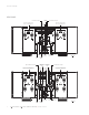
Control Connectors
Micro USB connector:
this connection enables the unit to be
connected to a computer for internal webpage discovery. For
more information on using the internal webpage, please see the
Settings section of this manual.
USB Type-A connector:
the connector is for attaching a USB
drive containing software update, or for importing setup
configurations. Further information on software updates is
available from the Settings section of this manual.
Ethernet connector:
This connector accepts a Cat5 or higher
cable for connection to a home network. The Ethernet
connection is a standard 10/100 connection for external control
and networking. The amplifier supports connection to a router,
network, or computer.
RS-232 connector:
This RJ-11 connector provides serial control
through a standard RS-232 connection. For a table of RS-232
commands please see the Appendix section of the manual.
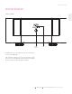
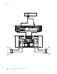
Trigger output connector:
This 1/8-inch (3.5mm) TS phone jack
can be used to activate other components in the audio system
and listening room, such as amplifiers, lights, and window
shades. A 12V 100mA DC signal is output whenever the unit is
on. (See illustration)
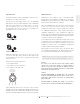
Trigger phone plug connector pin assignments:
• Tip: +
• Sleeve: –
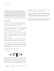
Trigger input connector:
this 1/8-inch (3.5mm) TS phone jack
can be connected to the trigger output of another system
component or control system that supplies a trigger voltage.
Whenever the unit detects a voltage between 3V and 12V DC at
this connection, it will turn On from Standby. When the trigger
signal at this connection ceases, the unit will enter the selected
Standby mode. When the Trigger Input is used to turn the
amplifier on, the Auto Off functionality is disabled.
AC Mains connector:
This connector provides AC power to the
unit when the supplied power cord is connected from it to an AC
electrical outlet. Unplug the amplifier from the AC wall outlet
during lightning storms and extended periods of non-use.
Power switch:
This mechanical switch turns the unit’s power
supply on or off. During normal operation, do not use the Power
switch to power off the unit; instead, use the Standby button.