
Specifications
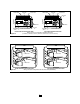

HORIZONTAL DISCHARGE (Rod-mount from Ceiling)
1. Install four threaded mounting rods in the threaded holes
and secure in place using lock nuts. (See Table 2).
2. Securely attach the four mounting rods to the ceiling. (Refer
to Table 1 for wall and ceiling clearances, and Table 2 for
mounting rod spacing).
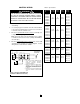
VERTICAL DISCHARGE (Rod-Mount from Ceiling)
1. Remove bolts from the threaded holes in the back of the
heater.
2. Install four threaded mounting rods in the threaded holes
and and secure in place using lock nuts.
3. Securely attach the four mounting rods to the ceiling. (Refer
to Table 1 for wall and ceiling clearances, and Table 3 for
mounting rod spacing dimensions.)
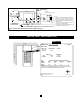
WIRING
BRANCH CIRCUIT (POWER)
1. Connect heater only to the voltage, amperage and frequen-
cy specified on the nameplate.
2. Field wiring must be properly sized to carry the amperage in
accordance with the NEC.
3. The access door is hinged. There are either one or two
screws accessible from the bottom, that must be removed
to gain access.
4. A knockout is provided in the back of the heater close to the
power terminal block and the control terminal board. The
control terminal board knockout is 1/2 inch (12.7 mm) con-
duit size. The power terminal block knockout is multiple
diameter. Use the diameter that fits the required conduit
size.
5. A ground terminal is provided near the power terminal
board. The ground wire should be connected before other
connections are made.
6. The power terminal board is equipped with box terminals
sized to accept the correct size power supply wire. Wire
rated at 600 V and 60° C is satisfactory for the heater
branch circuit. Either aluminum or copper wire is satisfac-
tory for connection to the heater power terminal board box
terminal. Copper wire is recommended and must be used
with built-in disconnect switch.
Table 2. Rod Thread and Spacing Dimensions, inches (mm)
for Horizontal Discharge
Rod Thread
Unit Type A B C D
3 - 5 kW
64
1
/
16
3
/
4
6
1
/
16
(152.4) (103.1) (19.0)
7.5 - 10 kW
(153.9)
15 - 20 kW
5
/
16
- 18
11
3
/
8
8
7
/
8
5
1
/
8
3
/
4
(289.0)
(225.6) (130.3) (19.0)
25 - 30 kW
10
9
/
16
14
1
/
2
6
3
/
16
5
/
8
(268.2) (368.3) (157.2) (16.0)
40 - 50 kW
3
/
8
- 16
15
15
/
16
14
1
/
2
6
3
/
16
5
/
8
(404.9) (368.3) (157.2) (16.0)
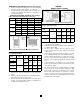
Figure 2. Vertical Discharge Mounting and Rod Spacing
Table 3. Rod Thread Type and Spacing Dimensions, inches
(mm) for Vertical Discharge
Rod Thread
Unit Type E F G H
3 - 5 kW
69
3
/
4
24
1
/
16
5
/
16
- 18
(152.4) 247.7) (50.8) (103.1)
7.5 - 20 kW
8
7
/
8
14
5
/
8
25
1
/
8
(225.6) (371.6) (50.8) (130.3)
25 - 30 kW
3
/
8
- 16
14
1
/
2
21
1
/
4
2
3
/
16
6
3
/
16
(308.1) (539.8) (55.6) (157.2)
3
Unit Discharge Ceiling Side Wall Back Wall
3 & 5 kW
Horiz. 2 (50.8) 6 (152.4) 9 (228.6)
Vert. 6 (152.4) 18 (457.2) 18 (457.2)
7.5 to 10 kW
Horiz. 6 (152.4) 6 (152.4) 13 (330.2)
Vert. 6 (152.4) 24 (609.6) 24 (609.6)
15 to 10 kW
Horiz. 6 (152.4) 9 (228.6) 12
1
/
2
(317.5)
Vert 6 (152.4) 24 (609.6) 24 (609.6)
25 to 50 kW
Horiz. 16 (406.4) 12 (304.8) 18
1
/
2
(470.0)
Vert. 12 (304.8) 36 (914.4) 36 (914.4)
Table 1. Wall and Ceiling Clearance, inches (mm)
Figure 1. Horizontal Discharge Mounting and Spacing.