
Specifications

4
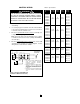
7. Each heater has a wiring diagram affixed to the inside of
the access door. Consult this diagram before making
any field connections.
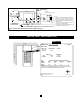
8. Single or three-phase power connections may be used
with heater models HUHAA520, HUHAA524,
HUHAA720, HUHAA724, HUHAA1020, HUHAA1024
and HUHAA1520. These units are factory wired for sin-
gle phase operation. If these heaters are for use with
three-phased power, reconnect the wires as indicated
in the wiring diagram attached to the heater. Additional
information can be found by looking at the wiring illus-
trations in Figures 3a and 3b and following the directions
shown below.
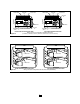
On models HUHAA520, HUHAA524, HUHAA720,
HUHAA724, HUHAA1020 and HUHAA1024 (Figure 3a),
move only the two wires marked “A1” and marked “B1”; do
not move or change any other wiring. The element lead wire
marked “B1” which is factory connected to the power termi-
nal block (terminal located closest to the elements) must be
moved to terminal “B” on the three-phase terminal block.
The relay (contactor) lead wire “A1” must be moved from the
end terminal of the power terminal block (terminal closest to
the contactor or control terminal board) to the “A” terminal of
the lower terminal block (center terminal).
Model HUHAA1520 (Figure 3b)has two three-phase terminal
blocks located adjacent to the relays (contactors). Move
only the two wires marked “C1” and “D1” on each of these
two three-phase terminal blocks to terminal “B”. Do not
move or change any other wires.
9. Electrical Accessories, either kits or factory-installed
options, are shown connected by a dashed line on the
heater wiring diagram.
10.
208/240 VOLT HEATER. Interchange transformer red
and black primary leads (see wiring diagram) when the
heater is to be connected to 208 volts supply.