
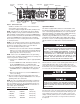
Specifications

INSTALLATION
INSTRUCTIONS
The heater is designed for recessed installation in 2” x 4”
(50 mm x 101 mm) studs or larger wall sections using the back
box provided. The heater may be wired with standard building
wire (60°C). Refer to “Specifications” and heater nameplate for
correct supply voltage and wire size.
NOTE: The optimum mounting height for this heater is 18” to 24”
(450 mm to 600 mm) from floor to bottom of back box. DO NOT
install closer than 12” (305 mm) from the floor.
Mounting Clearances
Wall Mounting Only:
a. Minimum twelve (12) inches (305 mm) to floor;
b. Minimum twelve (12) inches (305 mm) to adjacent walls;
c. Minimum thirty six (36) inches (915 mm) to ceiling.
Installation of Back Box in New Construction
(See Figure 1).
NOTE: If the finished wall surface is already up, follow instruc-
tions for “Installation of Back Box in Existing Construction”.
1. Place the back box between two 16" (406 mm) center-to-
center wall studs at the desired mounting height but no clos-
er than 12" (305 mm) to adjacent wall or floor.
NOTE: If wall studs are spaced greater than 16” (407 mm) on
center, additional framing supports may be necessary.
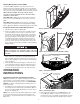
2. Align back box such that the bottom and sides will be flush
with finished wall surface (top flange of back box should pro-
trude approximately 1/2" (12.7 mm) from finished wall surface
(You must know the thickness of the finished wall when
installing).
3. Secure the back box in position with wood screws or nails as
shown in Figure 1.
4. Run a power supply cable into the knockout area in the upper
right hand corner of the back box (see Figure 1). All wiring
must be in accordance with National and Local Electrical
Codes. Refer to Specifications for correct wire size.
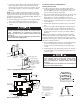
5. Remove disconnect switch bracket by loosening two screws
on the right side.
6. Install a cable clamp in the knockout in the top of the back
box.
To prevent a possible fire, injury to persons or damage to the
heater, adhere to the following:
1. Disconnect all power coming to heater at main service
panel before wiring or servicing.
2. All wiring procedures and connections must be in accor-
dance with the National and Local Codes having jurisdiction
and the heater must be grounded.
3. Verify the power supply voltage coming to heater matches
the ratings as shown on the heater nameplate.
CAUTION: ENERGIZING HEATER AT A VOLTAGE GREATER
THAN THE VOLTAGE PRINTED ON THE NAMEPLATE WILL
DAMAGE THE HEATER AND VOID THE WARRANTY AND
COULD CAUSE A FIRE.
4. CAUTION - High temperature, risk of fire, keep electrical
cords, drapery, furnishings, and other combustibles at least
3 feet (0.9 m) from front of heater. Do not install heater
behind doors, below towel racks, or in an area where it is
subject to being blocked by furniture, curtains or storage
materials. Hot air from the heater may damage certain fab-
rics and plastics.
5. To reduce the risk of fire, do not store or use gasoline or
other flammable vapors and liquids in the vicinity of the
heater.
6. For wall mounting only with air discharge downward. Do
NOT install in floor, ceiling, upside down (air discharge
upward), or sideways.
7. The following minimum clearances must be maintained:
Bottom of heater to floor - 12” (305 mm).
Sides of heater to adjacent wall - 12” (305 mm).
Top of heater to ceiling - 36” (915 mm).
8. Do not operate the heater without the back box.
9. Do not use this heater for dry out purposes as the paint,
plaster, sawdust and drywall sanding dust will permanently
damage the heater and must be kept out of the heater.
10. Remove motor shipping bracket and yellow tag prior to oper-
ating this heater.
TO PROVIDE FOR SAFE OPERATION, THE FOLLOWING
CLEARANCES MUST BE MAINTAINED.
TO PREVENT HAZARD OF FIRE OR ELECTRICAL SHOCK,
DO NOT INSTALL WITHOUT BACK BOX.
TO PREVENT POSSIBLE DAMAGE TO POWER WIRING,
USE ONLY THE KNOCKOUTS PROVIDED IN BACK BOX.
2
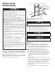
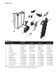
Figure 1: Locating Back Box in New Construction
Back Box
12” Min.
(305 mm)
Nail or screw
(2 each side)
12” Min.
(305 mm)
Disconnect switch
bracket with switch and
leads
Lead wires (Blue)
Power supply cable
Ground screw
Cable
clamp
(No disconnect
switch on
208V models)