
Specifications

7. Insert power supply cable through cable clamp, allowing at
least 6" (152 mm) of leads to extend inside the back box.
Connect the blue lead wires of disconnect switch to the sup-
ply wire leads using wire connectors (see Figure 4, Wiring
Diagram).
NOTE: If power supply is provided by standard non-metallic
sheathed cable (Romex) and the supply voltage is 240 or 208
volts (two power wires), the white wire color must be changed
using black electrical tape to comply with the NEC. White is only
allowed for a Neutral conductor.
8. Connect building ground conductor to the back box using the
green screw located in the inside top of the back box.
9. Secure disconnect switch bracket in place by tightening
screws.
Installation of Recessed Back Box in
Existing Construction
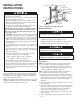
1. Provide a wall opening 14-3/4" (375 mm) wide by 18-1/2"
(470 mm) high at the desired mounting height, but no closer
than 12" (305 mm) from floor. (See Figure 2.) Locate so at
least one side of opening is at wall stud.
2. Run a power supply cable into the knockout area in the upper
right hand corner of the wall opening (see Figure 2). All
wiring must be in accordance with National and Local
Electrical Codes. Refer to Specifications for correct wire size.
3. Remove disconnect switch bracket by loosening two screws
on the right side.
4. Install a cable clamp in the knockout in the top of the back
box.
5. Insert power supply cable through cable clamp, allowing at
least 6" (152 mm) of leads to extend inside the back box.
Connect the blue lead wires of disconnect switch to the sup-
ply wire leads using wire connectors (see Figure 4, Wiring
Diagram).
NOTE: If power supply is provided by standard non-metallic
sheathed cable (Romex) and the supply voltage is 240 or 208
volts (two power wires), the white wire color must be changed
using black electrical tape to comply with the NEC. White is only
allowed for a Neutral conductor.
6. Connect building ground conductor to the back box using the
green screw located in the inside top of the back box.
7. Secure disconnect switch bracket in place by tightening
screws.
8. Insert back box in wall opening being careful not to damage
the supply wiring. Secure the back box in place with wood
screws or nails.
POWER SUPPLY VOLTAGE MUST BE THE SAME AS
HEATER VOLTAGE RATING SHOWN ON HEATER NAME-
PLATE. CONNECTING TO A VOLTAGE IN EXCESS OF
NAMEPLATE RATING WILL DAMAGE HEATER AND VOID
WARRANTY.
ALL CONNECTIONS MUST BE MADE WITH APPROPRIATELY
SIZED LISTED WIRE CONNECTORS.
POWER SUPPLY VOLTAGE MUST BE THE SAME AS
HEATER VOLTAGE RATING SHOWN ON HEATER NAME-
PLATE. CONNECTING TO A VOLTAGE IN EXCESS OF
NAMEPLATE RATING WILL DAMAGE HEATER AND VOID
WARRANTY.
ALL CONNECTIONS MUST BE MADE WITH APPROPRIATELY
SIZED LISTED WIRE CONNECTORS.
3
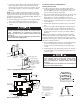
Figure 2: Locating Back Box in Existing Construction
12” Min.
(305 mm)
Nail or screw
(2 each side)
12” Min.
(305 mm)
14 1/2” Min.
(362 mm)
Disconnect switch
bracket with switch
and leads. (No discon-
nect switch on 208V
models)
Lead wires (Blue)
Power supply cable
Ground
screw
Cable
clamp
Back Box
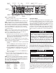
POWER BOARD
DISCONNECT SWITCH
(PROVIDED ON ALL MODELS
EXCEPT 208V/1P UNITS)
RED JUMPER WIRE FOR
BUILDING MANAGEMENT
SYSTEM CONNECTION
OVERHEAT
THERMISTOR
REGULATING
THERMISTOR
ELEMENT
MOTOR
TRIAC
V1
G
V2
J-JUMPER
TRIAC-N
EOL
LIMIT
SWITCH
L/N
*BLU
BMS
L1
L/N *BLK
BLK
L1
G
G1 G2
GRN
GRN GRN
E1
R1
C
D
E
(ON GRILL)
13
42
R2
RL-4
FAN-N
HIGH
LOW
YEL
WHT
BLK
TRIAC-LL
ELEMENT
Transformer
B
A
DATA CABLE
POWER
LIGHT
INFRARED
RECEIVER
OVERHEAT
LIGHT (see page 5)
DISPLAY BOARD
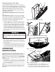
LEGEND
EOL END OF LIFE SWITCH
BMS BUILDING MANAGEMENT SYSTEM
G1, G2 GROUND SCREWS
J JUMPER
R1, R2 MANUAL RESET RELAY
FIELD WIRING
NOTES:
1. WIRES “C”, “E” AND JUMPER “J” ARE
SUPPLIED SOLDERED TO THE PC BOARD.
2. *BLK AND *BLU LEAD WIRES ARE IDENTIFIED
WITH WHITE TAPE AT EACH STRIPPED ENDS
TO INDICATE THAT THE NEUTRAL FOR THE
120V AND 277V MODELS ARE TO BE
CONNECTED TO THESE LEADS.
B
A
J3
J1
J2
J4
ELEMENT WIRING FOR 4800W, 208V/1PH
B
A
J5
ELEMENT WIRING FOR 4800W, 240V/1PH, 277V/1PH
& 1800W 120V/1PH
Figure 3- Wiring Diagram