
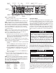
Specifications

Building Management Systems (BMS)
To utilize the BMS capabilities of this unit, remove the red
jumper wire between terminals A and B on the control terminal
board ( see figure 3, wiring diagram). Connect two wires from a
dry contact (no voltage) in the BMS system to terminals A and B.
NOTE: DO NOT REMOVE THE RED JUMPER UNLESS
THE UNIT IS BEING CONTROLLED BY A BUILDING MAN-
AGEMENT SYSTEM (BMS).
When BMS takes control, heater functions will not work, the
touch screen is locked, BMS light on the heater touchscreen
blinks.
When BMS releases control, heater functions are available,
heater resumes operating at previously programmed settings.
Refer to Operations Manual for programming options and details.
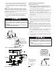
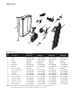
Installation of Grille and Control Wire Connector
1. Push disconnect switch into ON position.
2. Position the grille in front of the heater assembly, insert the
control shelf edges into the notches on either side of the
back box at the same time hooking the tabs on the bottom
corners of the grille assembly over the bottom flange of the
back box (see Figures 4 and 5). With the top of the grille
assembly leaning forward, supported by the first notch in
control shelf, extend the control wires from the back of the
electronic control at the top of the grille and connect to the
wires of the disconnect switch assembly according to Wiring
Diagram Figure 3.
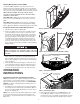
3. Lift and rotate the the grille assembly into the backbox care-
fully to ensure the control wire is not trapped between the
grille assembly and back box. Insert two screws at the top
edge of grille assembly on either side of the control panel as
shown in Figure 6.
4. Install (2) plastic bezels (left and right) on either side of the
control panel by inserting the wide tab under the flange on
the control panel as shown in Figure 7, rotating the narrow
end down and pressing firmly so the clip snaps into place.
OPERATION
INSTRUCTIONS
Initial Setup Instructions (Performed by Installer)
NOTE: After installation, the installer should perform the follow-
ing procedures to ensure proper operation of the heater (see
Figure 8 for Control Panel Layout). Refer to the OPERATIONS
MANUAL for details on programming and activating other fea-
tures of the heater.
1. Turn ON power to the unit at the main service panel. When
the heating unit is first powered up, it will default to ON. The
green power indicator LED will illuminate as long as there is
power to the heating unit.
NOTE: If the unit does not beep and the display does not light,
turn off power at the main service panel and check that the
Control Wire is connected and the Disconnect Switch is in the
ON position.
2 If the heating unit is OFF, touch the POWER button to turn
the unit ON (The display is a touch screen and does not
respond to pressure). The display should illuminate showing
the current room temperature and default program number,
THE HEATER ASSEMBLY MUST BE CAREFULLY POSI-
TIONED TO ENSURE THE CONTROL WIRES ARE NOT
TRAPPED BETWEEN THE HEATER ASSEMBLY AND THE
BACK BOX.
4
Figure 4- Installation of Heater/Grille Assembly
Figure 6- Securing Grille Assembly
Screw Locations
Figure 7- Securing Plastic Bezel
Clip
Plastic Bezel
Tab Under Flange
of Control Panel
Control
Shelf
Notches
Figure 5- Grille Assembly Detail, Grille Supported for Wiring
Flange
Tab
Back Box
Notch
Control
Shelf