
Installation Guide


Post MoUnt installation CONCRETE APPLICATION (continued)
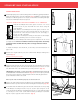
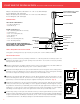
Fig. 4
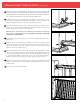
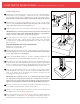
Fig. 5
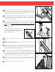
12
13
14
15
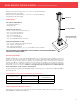
3/8" STAINLESS
STEEL HEX NUT
3/8" STAINLESS STEEL WASHER
3/8" COATED
HEX NUT
3/8" X 2" HEX BOLT
3/8" LOCK
WASHER
3/8" X 5 1/8"
STAINLESS STEEL
THREADED ROD
5/16" X 1" LEVELING BOLT
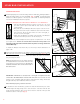
APPENDIX A: MARQUEE RAIL POST MOUNT SYSTEM INSTALLATION REQUIREMENTS AND LIMITATIONS
1 Installation of this post mount system requires the use of Hilti HIT-RE 500-SD Adhesive Anchoring System as described in
ICC-ES ESR-2322.
2 Installation must be in cracked or uncracked normal weight concrete with a specified compressive strength of 2,500 to 8,500 psi.
3 Use only the fasteners included with Marquee Post Mount Kits during this installation.
4 Installation condition must be dry.
5 Boreholes must be drilled using a hammer drill with ANSI B212-1994 approved 7/16” carbide bit, and cleaned as described in
ESR-2322.
6 Special Inspection and Jobsite Quality Assurance must be provided in accordance with Sections 4.4 and 4.5 of ESR-2322.
7 In service concrete temperature must be per Range A of Table 9 in ESR-2322. Max short term temperature = 110°F, Max long term
temperature = 80°F.
8 Applied torques to concrete anchors shall not exceed limits established by ESR-2322.
9 Installation must be in structures assigned to Seismic Design Categories A and B.
10 Installations are not subject to fatigue or shock loading.
11 For installations not consistent with the requirements and limitations noted above, calculations and details demonstrating compliance
must be prepared by a licensed professional engineer and submitted to the building official having jurisdiction in that area.
Otherwise, this installation could be improper and create a safety hazard.
NOTE: It may be necessary to slightly loosen the coated hex nuts to allow the post
mount member to be adjusted. Do not adjust the stainless steel hex nuts used for
concrete anchoring. When post is level, reapply 33 ft-lb torque on coated hex nuts.
Install the post ring over the concrete surface plate.
NOTE: For 38" Post Mount Systems, a portion of the 5-1/8" threaded rods may
need to be removed for proper post ring fit. If required, carefully trim the threaded
rods ensuring that a minimum of three threads remain above each of the stainless
steel nuts. (Fig. 4) Recheck and reapply the required torque on each of the hex nuts.
Install the two guide blocks onto the post mount member (Fig. 5). Position the
lower guide block at the bottom of the post and secure in place by installing one
of the supplied self-drilling screws through the center of the guide block and into
the post until firmly seated. Position the upper guide block so that the top of the
guide block is 1" above the top of the post member and secure in place by installing
one of the supplied self-drilling screws through the center of the guide block and
into the post until firmly seated.
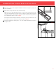
Trim the Marquee Post Sleeve (sold separately) to the desired length and install over
the post mount.
Apply PVC adhesive (not provided) to the post cap and install over the top of the post
sleeve. To install a Marquee Straight or Stair Rail Kit to the Marquee Post
Mount, use the 1-1/4" screws provided in the Marquee Straight or Stair Bracket kit.
Refer to the Marquee Straight or Stair Rail Installation Instructions for details.
10
CONCRETE POST MOUNT - FIGURE 4
THE UPPER GUIDE BLOCK
IS 1" ABOVE THE TOP OF
THE POST MEMBER
CONCRETE POST MOUNT -