
Installation Guide
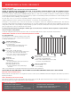
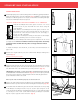
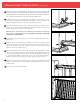
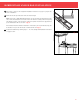
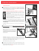
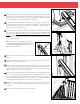
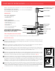
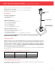
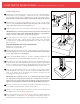

FIGURE 5
FIGURE 6
FIGURE 7
FIGURE 8
Attach the crush block included with the Marquee Rail Kit on the underside of the
bottom rail using the screw provided with the crush block. Center the mounting plate
on the deck surface so that it will be in line with the crush block installed on the bottom
rail. Screw the mounting plate to the deck using the supplied screw.
Insert bottom rail into the bottom rail brackets, making sure the rail is level. Secure
the bottom rail in place by installing two self-drilling 1" screws provided in the
Marquee Straight Bracket Kit on each side of the brackets. (Fig. 5)
Pull down on the bottom portion of the crush block until it sits flush with the deck
surface. Secure in position by installing the supplied retaining screw and color-
matched snap cap into the side of the crush block.
NOTE: Be sure to check with your local building code officials for any bottom
rail clearance or rail height requirements. Improper rail clearance or rail height
could cause a safety hazard.
Insert balusters into pre-routed holes on the bottom rail, making sure each one is
fully nested.
Align the top rail over the balusters and install one at a time into the pre-routed
holes. Ensure the top rail is fully nested and level with the bottom rail. Position
the top rail brackets on the rail, center the bracket on the post and mark the
bracket locations on each post. (Fig. 6)
Remove the brackets from rail. Tilt the rail outward from the post slightly to expose
the face of the post. Reposition the top rail brackets at the marked locations on
each post and install with screws provided in the Marquee Straight Bracket Kit. Use
2" screws when mounting to a wood post or the 1-1/4" screws when mounting to
Marquee Post Mount. (Fig. 7) Repeat on post at opposite end of rail section.
Slide the top rail into the top rail brackets and secure in place by installing two self-
drilling 1" screws provided in the Marquee Straight Bracket Kit on each side
of the brackets.
Attach the post cap using PVC adhesive.
Fig. 4
Fig. 5
Fig. 6
Fig. 7
10
11
12
6
7
8
9
13
straiGht rail installation (Continued)
3