
Installation Guide
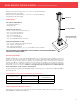

Marquee
™
Wood/Composite Post Mount Kit 5" x 5" x 38" for use with all Marquee
6' and 8' Railing Kits at 36" Rail Heights
Marquee Wood/Composite Post Mount Kit 5" x 5" x 44" for use with all Marquee
6' and 8' Railing Kits at 42" Rail Heights
COMPONENTS:
POST MOUNT COMPONENTS:
►Post Mount Member (1)
►Guide Blocks (2)
WOOD ACCESSORY KIT:
►3/4" Self-Drilling Guide Block Screws (4)
►Leveling Plate (1)
►5/16" x 1" Leveling Bolts (4)
►5/16" Washers (8)
►Back Plate (1)
►5/16" x 6" Mounting Bolts (4)
►5/16" Mounting Nuts (4)
SUBSTITUTION FOR THESE COMPONENTS IS
NOT ALLOWED AS SUBSTITUTING COMPONENTS
COULD CAUSE A SAFETY HAZARD.
TOOLS REQUIRED FOR INSTALLATION:
Safety glasses, hearing protection, tape measure, level, drill, 3/8" or 7/16" drill bit and wrench.
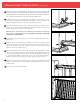
INSTALLATION STEPS:
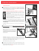
1 Reinforce post mount location by installing a minimum 3" of blocking under the mounting location. Cut
blocking to the length of the joist span opening and secure with 3" deck screws or nails (not provided)
directly under the deck surface.
2 Using the leveling plate as a template, mark the locations of the four mounting holes to be drilled. Drill four
holes through the deck and blocking using a 3/8" or 7/16" diameter drill bit.
3 Install the four leveling bolts into the post mount member. Place the leveling plate on the decking surface
and align over the four drilled holes. Place the post mount member on top of the leveling plate and align
the four holes. Adjust the leveling screws to ensure the post mount member is level.
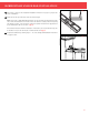
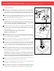
4 Install the four mounting bolts with washers as shown. On the underside, place the back plate over the
exposed mounting bolts. (Use the centered holes for in-line applications and the offset holes for corner
applications.) Secure the back plate by using the supplied mounting nuts and washers. (Fig. A)
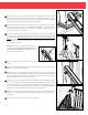
5 Install the two guide blocks onto the post mount member. Position the lower guide block at the bottom
of the post and secure in place by installing one of the supplied self-drilling screws through the center of
the guide block and into the post until firmly seated. Position the upper guide block so that the top of the
guide block is 1" above the top of the post member and secure in place by installing one of the supplied
self-drilling screws through the center of the guide block and into the post until firmly seated.
6 Position the post ring over the post sleeve and slide over the post mount system until the post sleeve is flush
to the deck surface. Attach the post cap to the post sleeve with PVC adhesive (not provided). To install a Marquee
Straight or Stair Rail Kit to the Marquee Post Mount, use the 1-1/4" screws provided with Marquee Straight
or Stair Bracket Kit. Refer to the Marquee Straight or Stair Rail Installation Instructions for details.
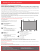
Post MoUnt installation WOOD/COMPOSITE APPLICATION
IN-LINE
INSTALLATION
CORNER INSTALLATION
IN-LINE
INSTALLATION
CORNER INSTALLATION
CORNER APPLICATION
INLINE APPLICATION
Fig. A
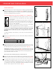
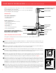
WOOD/COMPOSITE POST
MOUNT - FIGURE 2
THE UPPER GUIDE BLOCK IS 1" ABOVE
THE TOP OF THE POST MEMBER
GUIDE BLOCK SCREW
GUIDE BLOCK SCREW
MOUNTING BOLTS
WASHER
REINFORCEMENT SCREWS
BACK PLATE
WASHER/NUT
BLOCKING
DECKING
LEVELING PLATE
LEVELING BOLT
FRAMING
POST MOUNT MEMBER
7