
Installation Guide

Marquee
™
Concrete Post Mount Kit 5" x 5" x 38" for use with all Marquee
6' Railing Kits in 36" Rail Heights
Marquee Concrete Post Mount Kit 5" x 5" x 44" for use with all Marquee
6' Railing Kits in 42" Rail Heights
COMPONENTS:
POST MOUNT COMPONENTS:
►Post Mount Member (1)
►Guide Blocks (2)
CONCRETE ACCESSORY KIT:
►5-1/2" x 5-1/2" Concrete Surface Plate (1)
►3/8" x 2" Coated Hex Bolts (4)
►3/8" Coated Lock Washers (4)
►3/8" Coated Hex Nuts (4)
►5/16" x 1" Leveling Bolts (4)
►3/4" Self-drilling Guide Block Screws (4)
CONCRETE ANCHORING SYSTEM:
►3/8" x 5-1/8" Stainless Steel Threaded Rods (4)
►3/8" Stainless Steel Washers (4)
►3/8" Stainless Steel Nuts (4)
►Hilti HIT-RE 500-SD Adhesive, 11.1 oz. (1) (Hilti Dispenser Not Included)
SUBSTITUTION FOR THESE COMPONENTS IS NOT ALLOWED AS SUBSTITUTING COMPONENTS
COULD CAUSE A SAFETY HAZARD.
CONCRETE ANCHORS:
TAMKO
®
requires the use of the Hilti HIT-RE 500-SD adhesive anchoring system in the installation of this post
mount. The anchoring system must be installed in accordance with Hilti HIT-RE 500-SD Instructions and
ESR-2322. Concrete anchors must be installed in dry, normal weight concrete with a specified compressive
strength of 2,500 psi to 8,500 psi. In addition, it is the installer’s responsibility to ensure that the application
and conditions for use of this post mount are in accordance with the Requirements and Limitations provided
in Appendix A of these instructions. Failure to correctly anchor the post mount in accordance with the
above requirements could result in a safety hazard.
For more information regarding HIT-RE 500-SD adhesive anchoring, please contact Hilti at 1-800-879-8000 or
visit www.Hilti.com.
TOOLS REQUIRED FOR INSTALLATION:
Safety glasses, hearing protection, tape measure, round steel brush, compressed air, torque wrench, drill and
Hilti MD 2000 or compatible Hilti dispenser.
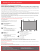
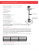
REQUIREMENTS FOR USE WITH MARQUEE 6' RAILING KITS:
Post Mount System Minimum Concrete Thickness
Minimum Threaded
Rod Embedment
38" 4-3/4" 3-1/2"
44" 5" 4"
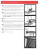
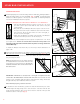
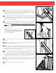
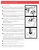
Post MoUnt installation CONCRETE APPLICATION
8
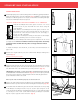
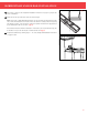
WOOD/COMPOSITE POST
MOUNT - FIGURE 2
THE UPPER GUIDE BLOCK IS 1" ABOVE
THE TOP OF THE POST MEMBER
GUIDE BLOCK SCREW
GUIDE BLOCK SCREW
MOUNTING BOLTS
WASHER
REINFORCEMENT SCREWS
BACK PLATE
WASHER/NUT
BLOCKING
DECKING
LEVELING PLATE
LEVELING BOLT
FRAMING
POST MOUNT MEMBER
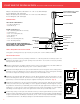
CONCRETE POST MOUNT - FIGURE 1
GUIDE BLOCK
POST MOUNT MEMBER
CONCRETE SURFACE PLATE
(See Fig. 4 for more details)