CASHFLOW® 9520 / 9524 / 9528 SELECTOR SYSTEMS DESIGN GUIDE MEI.
CashFlow® 9520 / 9524 / 9528 Design Guide PUBLISHED BY: MEI CashFlow® 9520 / 9524 / 9528 Design Guide Eskdale Road Winnersh Triangle Wokingham Berkshire RG41 5AQ United Kingdom. Internet: http://www.meiglobal.com For further information on editions in other languages please contact the Technical Communications Manager at the above address. ® CashFlow 9520 / 9524 / 9528 Selector Design Guide © , Mars, Inc., 2003.
CashFlow® 9520 / 9524 / 9528 Design Guide CONTENTS SAFETY.................................................................................................................................................................5 WARNING ............................................................................................................................................................5 CAUTION .....................................................................................................................
CashFlow® 9520 / 9524 / 9528 Design Guide Y-CHUTE INTERFACE CONNECTOR ....................................................................................................................25 DUAL ENTRY SYSTEM .......................................................................................................................................26 ELECTRICAL SPECIFICATION....................................................................................................................
CashFlow® 9520 / 9524 / 9528 Design Guide SAFETY Warning Before cleaning, servicing, removing or replacing CashFlow® units ALWAYS SWITCH OFF or ISOLATE the ELECTRICITY SUPPLY to the host machine. Caution This guide is recommended for use by personnel trained to carry out electrical installation.
CashFlow® 9520 / 9524 / 9528 Design Guide PRODUCT IDENTIFICATION MEI has manufactured coin mechanisms compatible with gaming and amusement machines for a number of years. Over this time the functionality of the range has been enhanced to match the market needs and whilst maintaining mechanical compatibility. The products detailed in this handbook relate to the CashFlow® 952x Series. To ensure you have the right product for your application please read this section.
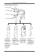
CashFlow® 9520 / 9524 / 9528 Design Guide Product Options; Front Plates Coin Entry Bezel Reject Button Coin Reject Exit Coin Catcher Hoop 7802 This model has a brushed stainless steel front plate suitable for external surface mounting. It is supplied complete with a coin catcher hoop, a coin entry bezel and a coin mechanism mounting plate assembly. © MEI., 2003 7804 7805 7819 This front plate is made of mild steel painted black and is a standard assembly suitable for internal mounting.
CashFlow® 9520 / 9524 / 9528 Design Guide Product Options; Reject Covers Reject Cover C B A C Type Coins Rejected Exit Accepted Coin Path B Type Coins Rejected Exit Type A Used with: Type B A Type Coins Rejected Exit Type C ® Used with: CashFlow 9520 ® Used with: ® CashFlow 9520 CashFlow 9520 CashFlow® 9524 CashFlow® 9524 ® CashFlow 9528 This type of reject cover is used on validators that are fitted with separators.
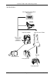
CashFlow® 9520 / 9524 / 9528 Design Guide Product Build Options Each product variant is made from the following components: Side Entry Product 7802 Front Plate Side Entry Validator 7804 Front Plate 7805 Front Plate CF9524 4-way Separator 7819 Front Plate © MEI.
CashFlow® 9520 / 9524 / 9528 Design Guide Top Entry Product Coin Entry/Token Entry Bezel (with electrics) CF9524/8 Y-Chute CF9524/8 Top Entry Validator Metal Channel CF9528 Short Channel (Supplied by machine manufacturer Manifold 4-way Separator 8-way Separator Tube Collar Plate © MEI.
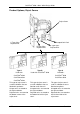
CashFlow® 9520 / 9524 / 9528 Design Guide DESCRIPTION & OPERATION 13 1 12 2 i™Button Memory 3 11 4 10 5 9 6 7 8 Key: 1 Coin Entry 2 Diagnostic ‘Bi-Colour’ LED 3 i-Button Memory Contacts 4 Support Tool Connector (CPM) CashFlow® Programming Module 5 Route Inhibit Connector 6 Serial Interface Connector (HII) 7 Separator Connector 8 8-way DIP Switch 9 Post Gate Strobes 10 Dual Polarity and BCO Interface Connector 11 Pre-Gate Strobes 12 Validator Lid 13 Reject Lever © MEI.
CashFlow® 9520 / 9524 / 9528 Design Guide Coin Entry (1) There are two types of coin entry available. Top entry and Side entry. • Top entry: The validator is mounted into the Channel and Coins enter through to top of the validator. • Side Entry: The validator is mounted onto the front plate and coins enter through the side of the validator.
CashFlow® 9520 / 9524 / 9528 Design Guide Post-Gate Strobes (9) The strobes are used to detect the direction & presence of coins passing through the validator. Dual Polarity and BCO Interface Connector (10) When in NON SERIAL mode, this interface is used to connect to the host machine. The functions provided are: • Coin outputs A, B, C, D, E, F. • Coin inhibits A, B, C, D, E, F.
CashFlow® 9520 / 9524 / 9528 Design Guide PRODUCT INTERFACES Standard Interfaces The standard interfaces available on CashFlow® 9520/9524/9528 validators are Parallel and Binary Coded Output (B.C.O.). The validator is supplied in Automatic Mode which senses the type of interface selected by the host machine via pin 8 (Output Mode Select) of the machine interface connector. Parallel Mode This type of interface is a standard 6 coin parallel output interface as used in the ME126/129 products (Dual Polarity).
CashFlow® 9520 / 9524 / 9528 Design Guide Binary Coded Output (BCO) - UK Defined by the validator coin output map. When in BCO mode coin output A is permanently set active to indicate to the host machine that the BCO feature is set. Coin output A will have a high impedance (approx. 1M Ohm to 0v) if coin output common is allowed to float. If an alarm condition occurs, coin outputs B, D, E and F will be activated.
CashFlow® 9520 / 9524 / 9528 Design Guide (BCO - EURO) Coin Output Coin No.
CashFlow® 9520 / 9524 / 9528 Design Guide Coin Validation Inhibits A, B, C, D, E, F To inhibit coin acceptance the CashFlow® validator offers six individual inhibit inputs. These inhibits operate for each mode as detailed in the following text. Binary Coded Output Mode Inhibits - UK The channels inhibited, for a given inhibit line becoming active are factory set by the validator coin inhibit map option. When inhibit (A to F) is active, then coins for the channels specified in the map will be inhibited.
CashFlow® 9520 / 9524 / 9528 Design Guide Automatic Mode - Parallel or BCO Selection In this mode the status of the output mode input (on pin 8 of the 17-way connector, or pin 7 for the 15 -way connector of the machine interface) selects either the parallel or the binary coded output interface standards. A logic high signal to this pin will select parallel mode, setting pin 8 to a logic low will select BCO mode. If there is no connection made to pin 8 the interface will default to parallel mode.
CashFlow® 9520 / 9524 / 9528 Design Guide ELECTRICAL INTERFACES Introduction This section gives the pin assignments for all connector interfaces used on the CashFlow® validators and it also includes timing diagrams of the signals appearing on the input and output lines. Connector 1, Machine Interface. The interface to the validator from the machine is exactly the same as those that apply to the MS/ME series validators, with the exception of pin 8 of the 17-way connector.
CashFlow® 9520 / 9524 / 9528 Design Guide Separator Connector (2) This connector is used for connection to the CashFlow® 9524 4-way or CashFlow® 9528 8way separators only. This is identified by a grey panel on the separator. Connector type used:- 20 way Molex DIL 901-42-0020. WARNING: Do not connect ME129, ME126 Active or ME126 Security separators to this product or damage may result. This is identified by a panel that has the facility to fit a route plug into the separator.
CashFlow® 9520 / 9524 / 9528 Design Guide Machine interface connector (Connector 1) Interface connections are via a 17-way header from the standard PCB. This header is a single row of 17 pins on a 0.1 inch grid. The pin size is 0.025 inch square. Figure 1 shows the interface connector and pin out Figure 1 2 3 4 5 6 7 8 9 10 11 12 13 14 15 16 17 1 2 3 4 5 6 7 8 9 10 11 12 13 14 15 16 17 Output Coin A Output Coin B Output Common Output Coin F n.c.
CashFlow® 9520 / 9524 / 9528 Design Guide Support Tool Connector (6-way) This connector can be found on the front of the acceptor and is used to reconfigure the ® validator using a MEI support tool e.g. (CPM) CashFlow Programming Module. Serial (HI2) Connector (10 - way) The position of this connector has been moved from the previous CF126 product and can now be found on the front face of the CF95xx. This provides easier access.
CashFlow® 9520 / 9524 / 9528 Design Guide ROUTING CONFIGURATION The CF9524 exits routes are marked as (B, C & D) with (A) being the default exit route * see below CF9524 4-WAY SEPARATOR Default Route = A CF9528 8-WAY SEPARATOR Default Route = 8 5 6 7 8 4 3 2 1 Cash Box Exits *Viewed from top see arrow above D 8 C 7 5 6 Coin Reject 2 1 A Coin Tube Exits B Default Route 4 3 Viewed from the top of the manifold assembly Default Route Coin Routing Priority The CashFlow® 9524/9528 differs fr
CashFlow® 9520 / 9524 / 9528 Design Guide Connector 4, Dynamic Route Inhibit This input from the host machine to the front reject cover of the validator is known as the Dynamic Route Inhibit. This inhibit signal indicates that a specific route has become full. To Inhibit a route the relevant pin should be grounded (i.e. active low to inhibit a route). Connector type used:- 9 pin SIL - AMP 925366. Route Inhibit Connector Pin No.
CashFlow® 9520 / 9524 / 9528 Design Guide Y-chute Interface Connector Connections to the Y-chute are made with a Molex type 6471 19-way. This connector is fitted to the dual entry (coin and token) system only. It provides an interface for the machine to inhibit acceptance of any coin/token and also gives a signal to the validator to inhibit coins during token input and to inhibit tokens during coin input. This interface is not supplied with the single entry system. © Pin No.
CashFlow® 9520 / 9524 / 9528 Design Guide Dual Entry System In dual entry systems the Y-chute forms the interface between the validator, Y-chute and the machine. The latter uses the Y-chute interface and the validator interface as its main connection points. The coin outputs are signalled from the validator interface. The coin inhibits are connected to the Y-chute interface and the inhibit signals are fed back to the validator interface by the host machine interface wiring, as shown below.
CashFlow® 9520 / 9524 / 9528 Design Guide ELECTRICAL SPECIFICATION Voltage Range 12V (+ 3V maximum, -2V minimum) Current Consumption; Quiesent (Idle) - 35mA Coin Flight - 65 mA Accept Gate only - 800 mA 2 Routing Solenoids - 2,300 mA for 320mS 3 Routing Solenoids - 3000 mA for 320 mS Coin Output Electrical Specification A B Logical Outputs C D E F o/p A o/p B o/p C o/p D o/p E o/p F 6X i/p o o/p XOR Polarity Sense Output Driver Block Vcc 4k7 o/p common 1K 10n 56R Output Circuit Block Diagram
CashFlow® 9520 / 9524 / 9528 Design Guide Output Common Specification Vcc R ohms (470) A B C Multiplexed D Bus E F A Cashflow B 126 C Outputs D E F OutputCom Rx10 (4k7) I= 6xVcc/R (150mA) Option Switches etc. Strobe 1 Strobe 2 Sample multiplexed implementation - Negative Common Strobe Output common can be left floating for multiplexed implementations. However the minimum turn on time when output common was floating is 15 micro seconds.
CashFlow® 9520 / 9524 / 9528 Design Guide Output Timings Negative Common Output Common Output to be Set o/p on Other Outputs o/p off T(o/p valid) = 15 micro seconds Positive Common Output Common Output to be Set Other Outputs o/p on o/p off BCO Mode is indicated by the A output being permanently active. This indicator can take up to 100 milliseconds to be established from power up. In order to ensure reliable operation of the host machine (i.e. coin mech.
CashFlow® 9520 / 9524 / 9528 Design Guide Positive Common Voltage Range Positive Common Operation (O/P Common) This interface is selected when pin 3 is greater than +4.5 volts with respect to pin 12. (0V) Output Common Voltage: +7 volts to +26 volts with respect to pin 12. Positive Common Outputs: On: Maximum current = 40mA Saturation voltage (Output common - Coin O/P) <1.
CashFlow® 9520 / 9524 / 9528 Design Guide Negative Common Voltage Range This interface is selected when pin 3 is <2.5V with respect to pin 12. (0V) Negative Common Outputs: On: Maximum current = 30mA O/P saturation voltage (Coin O/P - Opcom) <1.5V Off: 10 uA maximum at 27 volts (Coin O/P - OPcom) Pulse Width: Switched on for between 80 and 120 ms on acceptance of the appropriate coin.
CashFlow® 9520 / 9524 / 9528 Design Guide MECHANICAL INTERFACE DRAWINGS The following drawings are included in this section: CF9524 Front Plate Dimensions Drawing Number 32780 Front plate mounting detail. Drawing Number 32799 Standard front plate dimensions. Drawing Number 35811 Side entry space envelope. CF9524 Top Entry Mounting Space Envelope Drawing Number 35812. CF9528 Long Channel Mounting Space Envelope Drawing Number 35824 Long channel dimensions.
CashFlow® 9520 / 9524 / 9528 Design Guide © MEI.
CashFlow® 9520 / 9524 / 9528 Design Guide © MEI.
CashFlow® 9520 / 9524 / 9528 Design Guide © MEI.
CashFlow® 9520 / 9524 / 9528 Design Guide © MEI.
CashFlow® 9520 / 9524 / 9528 Design Guide © MEI.
CashFlow® 9520 / 9524 / 9528 Design Guide © MEI.
CashFlow® 9520 / 9524 / 9528 Design Guide © MEI.
CashFlow® 9520 / 9524 / 9528 Design Guide COMPATIBILITY Previously Used New Product Equivalent CashFlow® 111 & CashFlow® 9520 CashFlow® 115 CashFlow® 126 CashFlow® 9524 CashFlow® 129 CashFlow® 9528 © MEI.
CashFlow® 9520 / 9524 / 9528 Design Guide PERFORMANCE STANDARDS Power Supply Full Operating Voltage range: +10V to +15V DC (+12V nominal) Supply Voltage Ripple: Within Vmin to Vmax up to 100Hz, <250mV pk - pk for Frequency>100Hz Current consumption: • Quiescent current: 120mA Max • Max current: 3A Max ® (4 solenoids active, Cashflow 9528) Compliance Classifications The product is designed to the following standards for sale into European markets and will carry the “CE” mark.
CashFlow® 9520 / 9524 / 9528 Design Guide Power Supply Input Protection Overcurrent protection is not included in the product and must be provided as part of the machine. Recommended fuse rating at the rated supply of 12V is: 3A Slow blow EN60127 Other protection methods may be used providing their over current characteristics remain within the overall operating characteristics of the above fuse.
CashFlow® 9520 / 9524 / 9528 Design Guide ENVIRONMENTAL PERFORMANCE Temperature Range Normal operational range 10°C to 40°C Full operational range 0°C to 60°C Storage range -10°C to 75°C Max.
CashFlow® 9520 / 9524 / 9528 Design Guide Thermal shock Sudden changes of temperature may cause temporary degradation of performance. For continuous operation and specified performance within the full operational temperature range, the rate of change of temperature should not be greater than 10°C per hour, non condensing © • Vibration (through machine mounting) • Vibration 0.25g at 5Hz to 500Hz - pseudo random, flat bandwidth • Coin validation will not be affected. MEI.
CashFlow® 9520 / 9524 / 9528 Design Guide TRANSPORTATION The following apply to fully packaged units: Shock Half sine, 30g shock, 18ms dur BS 2011 Part 2.1 EA : 1977 Bump 1000 bumps 6ms duration at 25g BS 2011 Part 2.1 b : 1977 Drop - Free Fall 2 drops from 1m onto each face BS 2011 Part 2.1 ED : 1977 Drop and Topple 50mm drop onto each corner BS2011 Part 2.1 EC : 1977 © MEI.
CashFlow® 9520 / 9524 / 9528 Design Guide PRODUCT SUPPORT In addition to the MEI offices around the world an international network of Distributors and Approved Service Centres can offer you technical support and other services as well. ® These services include repairs, re-programming of your Cashflow products with new coinsets, replacing damaged modules, and the supply of a range of spare parts. FRANCE GERMANY G.T.I.
CashFlow® 9520 / 9524 / 9528 User Guide ITALY GREAT BRITAIN s.a.s. ERREMA di Temporiti & C EUROCOIN LTD Via dell’Industria 5-5/A Fortune House 20094 Corsico MI Moxon Street Contact: Felice Penzo Barnet Tel: +39 02 45 869762 Herts Fax: +39 02 45 869784 Contact: Steve Smith Tel: 0208 275 3000 V.A.T. Srl Fax: 0208 275 3030 VENDING ASSISTANCE TEAM VIA BENADIR, 14 EUROCOIN LTD 20132 MILAN Fortune House ITALY Moxon Street Contact: Mr.
CashFlow® 9520 / 9524 / 9528 Design Guide HELPING YOU DELIVER YOUR REPRESENTATIVE