
Manual

4
3. Turn handle of appropriate regulator counter-clockwise until spring in
regulator is completely relaxed.
4. Turn handle of selector valve to appropriate position.
5. Turn on air supply, adjust pressure to desired value with regulator
and compare gauge reading with the calibrator reading.
2.2.4 Calibration of Pneumatic Recorders or Indicators
1. Connect air supply and recorder or indicator as in 2.2.3, sentence 2
or 3 above.
2. Proceed as in 2.2.3, sentence 4 and 5, comparing recorder pen
reading or indicator pointer reading with calibrator reading.
2.2.5 Measurement of Pressure Differentials from External
Sources
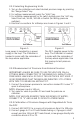
1. Connect higher of two pressures to P3.
2. Turn selector valve handle to position P3.
3. Apply lower of two pressures to “S” and read difference in pressure
on calibrator.
CAUTION: DECREASE REFERENCE PRESSURE TO ZERO OR SHUT
IT OFF BEFORE SHUTTING OFF OR DISCONNECTING PRESSURE
CONNECTION ON P3.
2.2.6 Calibration of Pneumatic Controller in Which Applied Set
and Variable Pressures Result in an Output Pressure Which is
a Function of the Other Two Pressures
1. Connect AIR SUPPLY to a source of air pressure not exceeding 100
psig.
2. Connect Pl to SET pressure connection on control device.
3. Connect P2 to PROCESS VARIABLE pressure connection on control
device.
4. Connect OUTPUT connection on control device to P3.
5. Turn regulator handles counter-clockwise until spring in regulator is
completely relaxed.
6. Turn on air supply.
7. Turn selector valve to position Pl and adjust Regulator 1 until SET
pressure displayed on calibrator is the value required by the
particular device.
8. Turn selector valve to position P2 and using Regulator 2 set the
PROCESS VARIABLE to the desired value.
9. Turn selector valve to P3 and read the OUTPUT pressure resulting
from action of P1 and P2 on controller.
10. Repeat steps 9 and 10, at various points, as many times as desired
to cover the range of PROCESS VARIABLE pressure.