
Manual

2.2.7 Adjustment of Any Pneumatic Device in Which the
Difference Between Two Signals Should Be Zero or Some
Value Not Exceeding the Range of the Calibrator
1. Connect the two signals to P3 and “S” respectively with the higher
pressure on P3.
2. Turn selector valve to P3.
3. Turn on the two signals simultaneously if possible. Otherwise turn on
P3 first. WARNING: TO AVOID POSSIBLE SEVERE PERSONAL
INJURY OR EQUIPMENT DAMAGE, THE PRESSURE APPLIED TO
“S” MUST NOT EXCEED 105 PSI.
2.2.8 Measurement of Absolute Pressure
1. Connect vacuum pump to “S” and evacuate the low side of the
differential sensor (as close as possible to a full vacuum). The
reading will indicate pressure below atmosphere (vacuum).
2. Connect pressure to be measured to P3.
3. Turn selector valve to P3 and read absolute pressure.
2.2.9 Calibrating Pressure Transmitters (P/I Devices)
1. Connect AIR SUPPLY to a source of air pressure not exceeding 100
psig.
2. Connect Pl or P2 to the pressure input on the device under test.
3. Turn regulator Rl handle counter-clockwise until completely relaxed.
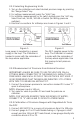
4. Make electrical connections in series with the current loop per
diagram in Figure l.
5. Turn on air supply.
6. Adjust air pressure to desired setting using regulator Rl.
7. Read pressure and current on display.
8. To check zero and span or mid-range values, repeat steps 7 & 8 at
desired test points.
2.2.10 Verifying Pressure Switches
1. Disconnect any electrical connections to the switch being tested.
2. Connect the pneumatic (pressure) input of the switch to one of the
DPC’s outputs.
3. Press the “mA” key until the word “SWITCH” appears on the display.
4. Connect the pressure switch output to the +24 and + mA jacks on
the DPC as shown in figure 2.
5. The display will indicate “OPEN” or “CLOSED” depending on
continuity.
6. Adjust the pressure output and note the pressure readings when the
switch display changes between “OPEN” and “CLOSED”.
7. Repeat this test with both rising and falling pressures to determine
pressure switch hysteresis (deadband).
5