
Instructions / Assembly

Each carton contains one top section, one
b
ottom section (larger trees include one or
more middle sections) and a tree stand.
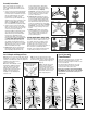
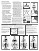
1. Unfold the tree stand and insert the eye
bolt. Remove packing material from ends
of poles. Put bottom section pole into tree
stand making sure it is seated properly
(Figure 1). Tighten eye bolt until bottom
section is held securely.
2. Insert the top tree section into the green
plastic opening of the lower tree assembly.
This is the “pole cap” which keeps tree top
s
ection securely in place (Figure 2).
P
owerConnect® trees will not have a pole
cap. Center pole of top section simply
inserts into center pole of section below.
For larger trees with middle section,
carefully insert middle section pole(s) into
bottom section pole (Figure 3) as instructed
in SPECIAL NOTE ABOUT GIANT TREES
below. Then insert top section into pole cap.
Optional: You may want to lubricate middle
section pole ends prior to assembly. This will
make sections easier to separate when
disassembling for storage.
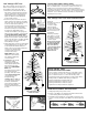
3. (Figure 4) Each tree section has a light string
cord that will plug into a receptacle on the
section below. Note that the male and
female connectors are keyed and will only
connect in one direction. After
connection, twist closed each
connector nut securely.
GIANT TREES that include
additional sections will also
have additional light string
cord connections.
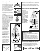
4. SHAPING: Branches should
fall into place during
assembly. If any branches
remain upright, gently lower
them into proper position
(Figure 5). See IMPORTANT
NOTE below.
Each branch must be shaped
to a natural position by
spreading out the tips. Please
follow Shaping Instructions
on next page for proper
shaping technique.
MEMORY SHAPE
®
TREES do
not require branch shaping.
Branches should fall into
place during assembly. If any
branches remain upright,
gently lower them into proper
position.
Fig. 4
Important Note: When lowering
branches be extremely careful not
to tangle wire in gap between
branch and bracket.
Not all low voltage trees
include foot switch
Low Voltage LED Trees
3
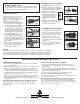
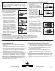
BULB REPLACEMENT INSTRUCTIONS
1. Unplug light string from power source.
2. Pull up on the Bulb Lock unlatching the bulb from the bulb
socket. Gently pull the bulb straight out.
3. Carefully insert new bulb into socket (bulb is keyed and only
goes in one way) and push down Bulb Lock until it snaps into
place.
DUALCOLOR
®
TREE
OPERATING INSTRUCTIONS
The foot switch operates the functions of the lights. There
are nine functions, each one is activated with the press of
the foot switch. Functions occur in the following order:
Steady warm white; Steady multicolor; Fading warm white;
Fading multicolor; Warm white fading to multicolor;
Flashing warm white; Flashing multicolor;
Flashing warm white to multicolor (slow);
Flashing warm white to multicolor (fast)
Light functions always follow this sequence.
F
ig. 6
Low Voltage LED Trees with PowerConnect
®
(Figure 6)
PowerConnect trees do
not require the
conection of light
strings between
s
ections. Electrical
connections are made
when each section is
assembled.
Following assembly
and shaping, connect
the light the electrical
cord at base of tree into
a power supply.
During tree assembly
or disassembly, DO
NOTDISCONNECT
any of the factory
connected light strings
that are located on
the center pole or
within the tree.
Fig. 1
Fig. 2
Fig. 3
Fig. 5
SPECIAL NOTE ABOUT GIANTTREES
Some of the larger trees in our product line will include more
than one middle section. If your tree contains more than one
middle section, note that each section will be numbered in
ascending order. The tree bottom section (which inserts into tree
stand) will be number 1. The next section as you build up, will be
number 2. Section 3 will follow until assembly is completed by
inserting tree top section.
Not all low voltage trees
include foot switch