SWB500I DELUXE RADIANT WOOD BURNING FIREPLACE INSTALLATION, OPERATION AND MAINTENANCE MANUAL The SWB500I fireplace is an insulated radiant wood burning fireplace with a 42-inch wide front opening. It comes complete with an interior damper to prevent heat loss when not in use, and it has fire screens for safe use. The SWB500I fireplace may be installed in residential and manufactured type homes as explained by this instruction manual.
CONGRATULATIONS! You have chosen a fine woodburning fireplace. Your fireplace has been designed and built for years of heating and viewing enjoyment. Please take time to read this entire manual before installing or operating your fireplace. TABLE OF CONTENTS LISTING AND CODE APPROVALS ............................................................................................................... 2 CAUTIONARY INFORMATION ........................................................................................
CAUTIONARY INFORMATION 2 1. Read these instructions entirely before beginning any part of the installation. Save these instructions for any future repairs. 2. Use these instructions as a guide during the installation of the fireplace. 3. Be sure these instructions become the property of and are reviewed by all future users of this fireplace to encourage proper operation and maintenance. 4. All the parts used with this fireplace system must be installed in accordance with these installation instructions.
OPERATION GUIDELINES 5 As wood is burned in the fireplace, room air entering the fireplace through vents is circulated around the firebox of the fireplace. This air circulation protects the firebox from overheating. Fireplace vents must not be blocked or restricted in any manner. Blocking or restricting air circulation through the fireplace can cause a fire hazard.
6 OPERATION GUIDELINES supplied, this can cause a negative pressure in the home. When this happens, the house will draw in outside air from the cracks in the windows, down the fireplace flue or other locations of air leakage in the home. Because cold air infiltration may be unavoidable in some structures, Monessen Hearth Systems is not responsible for heat loss or air infiltration through or around the fireplace.
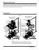
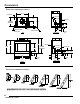
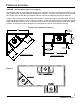
CLEARANCES FIGURE 2 (ALL DIMENSIONS IN INCHES.) 29 1/8 1" AIR SPACE OUTSIDE AIR GAS LINE 9 1/2 FRONT 25 3/4 FRAMING DIMENSION 25 1/4 9 1/4 8 3/4 10 1/4 11 1/2 1/2 (REF) NAILING FLANGE (EACH SIDE) 15 7/8 FRONT FACE LINE TOP FLOOR LINE LEFT SIDE 44 38 1/4 44 1/4 FRAMING DIMENSION 38 3/4 21 7/8 FRONT JUNCTION BOX 8 8 3/4 4 3/4 9 1/2 3/4 42 44 44 1/2 OUTSIDE AIR GAS LINE 9 1/4 3/4 11 1/2 FLOOR LINE FLOOR LINE 15 7/8 RIGHT SIDE FRONT FIGURE 3 (ALL DIMENSIONS IN INCHES.
FIREPLACE LOCATION CAUTION: Do not install fireplace over carpeting. This fireplace does not weigh more than large pieces of furniture and can normally be located near a load bearing wall without requiring additional foundations or supports. If however, the fireplace is to be trimmed with a heavy stone or brick facing and hearth extension, be sure the supporting structure is adequate.
INSTALLATION PREPARATION Survey the planned location for the fireplace for overhead plumbing or electrical wires, etc., that might complicate the installation or endanger persons installing or cleaning the chimney. Avoid a location where the chimney cap will be near abrupt changes in the roof shape, nearby wall or embankments, under or near trees or above the roof of a single story wing of a two story building as shown by Figure 8.
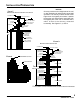
INSTALLATION PREPARATION NOTICE: Chimney must be correct height above the roof or other obstruction for safety and for proper draft operation. The chimney must be at least 3 feet higher than the highest point where it passes through the roof and at least 2 feet higher than the highest part of the roof or structure that is within 10 feet of the chimney, measured horizontally. See Figures 7, 9, and 14.
FLOOR PROTECTION If this fireplace is installed on a combustible floor, the floor area 20 inches in front of, and 12 inches either side of the fireplace opening must be protected by an insulating noncombustible hearth extension. This hearth extension may be either minimum 6-inch thick stone or brick as shown by Figure 10, a H2066 Hearth Extension Kit or a locally constructed hearth equivalent to the H2066. The insulation used in the H2066 hearth extension has a thermal conductivity (K Factor) of .43.
FLOOR PROTECTION The ability of insulating material to retard the transfer of heat may be expressed as either Thermal Conductance (C), Thermal Conductivity (K), or Thermal Resistance (R). The mathematical relationship of these values and the formulas for converting one value to another is as follows: C = K divided by the material thickness (Example C = .43 divided by 1/2 (.50) C = .86) K = C multiplies by the material thickness (Example K = .86 multiplied by 1/2 (.50) K = .
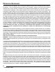
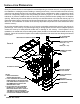
FIREPLACE COMPONENTS FIGURE 13 MLK42 LOUVER KIT 612 OR 1212 FLASHING AK4 OR AK6 COMBUSTION AIR ASSEMBLY CF8 CHIMNEY CAP 12 53D9034.
FIREPLACE COMPONENTS SEE FIGURE 13 FOR ILLUSTRATION OF MODELS DESCRIBED BELOW. MLK42 Louver kit to convert fireplace from radiant style to circulator style. GD42B 42-inch glass door kit with black trim. GD42PB 42-inch glass door kit with polished brass trim. H2853 * Canopy which may be installed on the fireplace to allow for the reduction of the recommended clearance to a combustible mantel. SCS Chimney support (required when chimney height exceeds 30 feet).
FIREPLACE INSTALLATION LOCATION SELECTION Unpack and check the fireplace and chimney for damage. If any items have been damaged, report this to your dealer. Before beginning the installation, be sure you have the proper parts in sufficient quantity. Refer to the Parts Diagram and List section of this manual for proper identification of parts. Do not substitute parts. Use only parts listed for use with Model SWB500I fireplace. FIREPLACE INSTALLATION 1.
CHIMNEY INSTALLATION FIGURE 14 SC CHIMNEY CAP 2 FEET MIN. 3 FEET MIN. APPLY MASTIC HERE 10 FEET STORM COLLAR FLASHING ROOF CAUTION: FOR SAFETY AND FOR PROPER DRAFT OPERATION, THE CHIMNEY MUST BE AT LEAST 3 FEET HIGHER THAN THE HIGHEST POINT WHERE IT PASSES THROUGH THE ROOF, AND IT MUST BE AT LEAST 2 FEET HIGHER THAN THE HIGHEST PART OF THE ROOF OR STRUCTURE THAT IS WITHIN 10 FEET OF THE CHIMNEY. CHIMNEY MUST NOT EXTEND MORE THAN 90 INCHES ABOVE THE ROOF WITHOUT ADDITIONAL SUPPORT. 1.
CHIMNEY INSTALLATION TABLE 1 FIGURE 15 CENTERLINE OF CHIMNEY ACTUAL CENTER POINT PLUMB LINE PLUMB BOB IMAGINARY CENTER POINT MINIMUM REQUIRED ROOF OPENING MINIMUM FRAMED OPENING ROOF PITCH "S" SERIES DOUBLE WALL CHIMNEY 0/12 1 12 2/12 3 12 4/12 5 12 6/12 7 12 8/12 9 12 10/12 11 12 12 12 14 1/2" x 14 1/2" 14 1/2" x 14 5/8" 14 1/2" x 14 3/4" 14 1/2" x 15" 14 1/2" x 15 1/4" 14 1/2" x 15 3/4" 14 1/2" x 16 1/4" 14 1/2" x 16 7/8" 14 1/2" x 17 1/2" 14 1/2" x 18 1/8" 14 1/2" x 18 7/8' 14 1/2" x 19 3/4" 14
CHIMNEY OFFSET INSTALLATION ELBOW INSTALLATION Following are important points that should be observed when installing elbows on the fireplace: 1. The support straps of all elbows not installed directly on top of the fireplace should be nailed securely to the surrounding structure. This allows the support strap to carry the weight of the chimney above the elbow and prevents this weight from breaking the elbow or chimney sections apart. See Figure 18. 2.
CHIMNEY OFFSET AND CAP INSTALLATION FIGURE 20 FIGURE 19 14-1/2" CL 22-1/16" CONTINUE CHIMNEY TO PROPER HEIGHT AND INSTALL ROUND CHIMNEY CAP OR CHIMNEY HOUSING. STORM COLLAR FLASHING /4" 7-1 " /16 7-9 SF FIRESTOP SPACER. ROOF 1-3/4" MINIMUM AIR SPACE CLEARANCE TO COMBUSTIBLES. 30˚ CENTERLINE OF CHIMNEY SF30 FIRESTOP SPACER FASTEN SUPPORT STRAPS SECURELY CL FIGURE 21 CONTINUE CHIMNEY THROUGH ROOF AND INSTALL ROUND CHIMNEY CAP OR CHIMNEY HOUSING.
CHIMNEY CAP INSTALLATION MODEL SC CHIMNEY CAP SPECIAL NOTE: The proper height as previously explained is important to assure proper draft and safety. The chimney cap extends the flue outlet four inches above the top of the last section of chimney. This should be kept in mind when determining the proper height for the chimney. The chimney should not be extended more than 90 inches above the supporting roof structure without additional support.
CHIMNEY HEIGHT AND OFFSET CHARTS TABLE 2 STRAIGHT RUN CHIMNEY SECTIONS HEIGHT (INCHES) 35 39 47 52 58 64 70 75 82 87 94 99 105 111 117 122 129 134 141 146 152 158 164 169 176 181 188 193 199 205 211 216 223 228 235 240 246 252 258 263 270 275 282 287 293 293 305 310 317 322 329 334 340 346 352 357 364 369 376 INTERMEDIATE SECTIONS 48" 36" 12" 18" 0 0 1 0 2 1 0 0 0 0 0 1 0 1 1 0 1 0 0 1 0 1 0 1 0 0 2 0 1 1 0 1 0 0 1 1 0 1 2 0 0 0 0 2 0 1 1 1 0 0 3 0 0 1 0 2 0 0 2 1 0 1 3 0 0 0 1 2 0 1 2 1 0 0 0 3 0 1 1 2
CHIMNEY CAP CHASE INSTALLATION The preinstalled chimney sections should be no more than 10 inches below the top of the chase. The installation should be planned so that either an 18-inch or 36-inch chimney section will be used for the top section. This is necessary to ensure complete engagement of the inlet air telescope and chimney cap into the top section. CAUTION: Be careful around electrical wires to avoid the electrical shock hazard of contacting the wires with the metal chimney components.
OUTSIDE COMBUSTION AIR PRECAUTIONS & RECOMMENDATIONS NOTICE: Outside air for combustion is optional in residential type installations unless required by local codes; it is mandatory in manufactured home installations. An AK4 outside combustion air kit is offered for use in residential type installations. An AK6 outside combustion air kit must be used in manufactured home installations.
OUTSIDE COMBUSTION AIR PRECAUTIONS & RECOMMENDATIONS 1. Extremely long runs and numerous turns in the duct leading from the fireplace to the combustion air assembly should be avoided. These conditions will increase the resistance to the free flow of air through the duct. See Figure 27 for methods of installing the outside air for combustion assemblies. 2. The combustion air assembly should be located at an exterior location, which is not likely to be accidentally blocked in any manner.
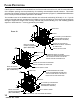
COMBUSTION AIR ASSEMBLY TO INSTALL THE OUTSIDE COMBUSTION AIR KIT 1. Remove the cover plate from the outside air opening located on the left OR right side of the fireplace. DO NOT remove the cover plate if the outside air will not be connected. 2. Insert the outside air starting collar into the hole on the side of the fireplace chosen by step 1 above. Fasten the collar in place with the four sheet metal screws provided. See Figure 24. 3.
GAS APPLIANCE INSTALLATION 2. 3. 4. 5. 6. 7. 8. Fireplaces, ANSI Z21.60. If a decorative gas appliance is installed, it must be installed in accordance with the National Fuel Gas Code, ANSI Z223.1. CAUTION: When a decorative gas appliance is installed, the fireplace damper must be set in the fully open position at all times. Only unvented gas log sets which have been found to comply with the Standard for Unvented Room Heaters, ANSI Z21.11.2, are to be installed in this fireplace. If an approved ANSI Z21.
GAS APPLIANCE INSTALLATION FIGURE 28 GAS LINE PLUMBING OUTER FIREPLACE WRAP SIDE REFRACTORY BRICK BACK REFRACTORY BRICK INNER FIREPLACE WRAP SIDE BRICK MAINTAIN 1/2" MINIMUM AIR SPACE CLEARENCE TO COMBUSTIBLES FOR GAS LINE OUT TO 4" FROM SIDE OF THE FIREPLACE. HEARTH BRICK GAS LINE ACCESS TUBE CAUTION: WHEN USING A GAS APPLIANCE, THE FIREPLACE DAMPER MUST BE SET IN FULLY OPEN POSITION. KNOCKOUT COMBUSTIBLE MATERIALS MAY BE LOCATED AT ZERO CLEARANCE TO GAS LINE BEYOND 4" FROM FIREPLACE SIDE.
TRIM INSTALLATION INSTALLATION OF NONCOMBUSTIBLE TRIM MATERIALS TO THE FRONT FACE OF THE FIREPLACE COMBUSTIBLE FRAMING MEMBERS FACING MATERIAL TO TOP OF SPACERS. NONCOMBUSTIBLE FACING MATERIAL USE ONLY NONCOMBUSTIBLE MATERIALS BELOW TOP OF SPACERS. FIREPLACE FACE FIGURE 29 STEEL LINTEL (OPTIONAL) CAUTION: DO NOT COVER OR RESTRICT VENT AREAS WITH ANY TRIM MATERIALS. WARNING: THE SPACE BETWEEN THE FACE OF THE FIREPLACE AND THE NONCOMBUSTIBLE FACING MATERIAL MUST BE SEALED.
GLASS DOOR INSTALLATION AND FAN ACCESSORY GLASS DOOR INSTALLATION This fireplace has been tested and listed for use with Model GD42B or GD42PB glass doors. For installation of the Model GD42B or GD42PB glass doors, see the instructions provided with the doors. FAN ASSEMBLY The SWB500I fireplace may be equipped with an FA2 fan IF the fireplace is also equipped with optional MLK42 Louver Kit. See Figure 13.
FIREPLACE OPERATION WARNING: If a decorative gas appliance is used in the fireplace the fireplace damper must be fixed in an open position. (See additional operation information in section titled “Operation Guidelines”.) WHICH WOODS ARE BEST? Each wood species offers something different in aroma or heat value, and you should consider your needs and desires before building your fire. Softwoods, like pine, spruce, and fir are easy to ignite because they are resinous.
FIREPLACE OPERATION You’ll need a minimum of three logs, preferably four, to make a good fire. Add kindling and new logs as needed to rekindle a dying fire. New logs should be added at the rear grate after raking the coals toward the front. DO NOT OVERFIRE THE FIREPLACE. Overfire conditions may be created by large amounts of kindling, building scraps, or other improper fuels.
MAINTENANCE AND SAFETY FUEL STORAGE Wood can be dried sufficiently for burning within a few weeks if protected form rain in a low humidity area. It is far better to cut wood and allow it to dry for a year. In all cases, the wood should be stacked so that both ends of the sticks are exposed to the air and protected from rain. The drier the wood, the more usable heat produced by the fire and less likely rapid accumulation of soot and creosote within the chimney is to occur.
MAINTENANCE AND SAFETY FIREPLACE MAINTENANCE At the end of each heating season or when the fireplace will not be in use for an extended time, the ashes should be removed and the hearth area should be swept as clean as is practical. The slow absorption of moisture into the ashes over a long period of time could cause a condition which would be corrosive to the metal fireplace parts.
MAINTENANCE AND SAFETY 20. Do build fires of moderate intensity in the fireplace for the first three fires to allow materials to adjust and cure before being subjected to the intense heat of a large fire. DON’TS 1. Don’t allow other installations or operation considerations to take priority over safety considerations. 2. Don’t attempt to use the fireplace until the installation is complete. 3. Don’t use unlisted parts and accessories with the fireplace except for special flashings fabricated locally. 4.
PARTS DIAGRAM AND LIST All repair part orders should be placed through your local dealer. To ensure prompt and accurate service, please provide the following information when placing a repair part order: Model number of your Appliance, Part Name, Part Number, and Quantity of parts needed. See Figure 34. Technical Service Department 2813 W. Mall Drive, Unit B. Florence, Alabama 35630. Tel. - 1-866-500-5671 www.monessenhearth.com FIGURE 34 1 2 3 4 5 6 (NOT SHOWN) 7 8 9 10 SWB500I FIREPLACE KEY NO.
THIS PAGE INTENTIONALLY LEFT BLANK. 35 53D9034.
LIMITED WARRANTY FACTORY-BUILT FIREPLACE AND COMPONENTS (EXCEPT BLOWERS) WHAT IS COVERED AND FOR HOW LONG • FIVE-YEAR COVERAGE - For five years from the date this fireplace and components are first purchased for use, Monessen Hearth Systems will, at its option, repair or replace any defective part of this fireplace or components, or refund to you a sum not to exceed the factory retail price in effect at the time of purchase.
LIMITED WARRANTY YOUR DUTIES This fireplace must be installed by a qualified installer according to your local building codes and installation instructions and operated according to the owner’s instructions. You must keep an invoice, canceled check or payment record to verify the purchase date of the fireplace. IF YOU HAVE A PROBLEM WITH YOUR FIREPLACE OR COMPONENT 1. Contact the nearest dealer. If you cannot locate your dealer, call or write Monessen Hearth Systems as indicated below. 2.
THIS PAGE INTENTIONALLY LEFT BLANK. 38 53D9034.
THIS PAGE INTENTIONALLY LEFT BLANK. 39 53D9034.
ATTENTION APPLIANCE INSTALLER: PLEASE RETURN THIS INSTRUCTION MANUAL TO THE CONSUMER. 53D9034.