
Owner manual

D-178
Installation/
Tensioning V-Drives
V-BELT DRIVES
Installing A Drive
Here are a few suggestions to keep in mind when installing
the drive:
1. Use a matched set of belts.
2. Clean oil and grease from the sheaves; remove any rust
or burrs from the sheave grooves.
3. Shorten the center distance of the drive until the belts
can be put on the sheaves without forcing.
4. Make sure that the sheaves are correctly aligned, that the
shafts are parallel, that there is clearance for the drive to
run and that the bearings have oil.
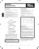
5. Work belts around in the groove by hand, so that the
slack of all belts is on the top, or slack of all belts is on
the bottom.
LIKE THIS:
(all slack at top)
OR LIKE THIS:
(all slack at bottom)
DO NOT APPLY THIS WAY:
(with slack at top and bottom)
Do not apply with the slack of some belts on the bottom
(see solid line) and the slack of others on the top (see
dotted line). Since V-belts will not slide in the groove,
belts thus applied will be injured when tightened for
operation.
Now tension the drive until only a slight bow appears on
the slack side of the belts when they are operating.
6. In a day or so, when the belts have had time to seat in
the grooves, re-tension the belts.
Tensioning The Drive
General Rules of Tensioning:
1. Ideal tension is the lowest tension at which the belt will
not slip under peak load conditions.
2. Check tension frequently during the first 24-48 hours of
run-in operation.
3. Overtensioning shortens belt and bearing life.
4. Keep belts free from foreign material which may cause
slip.
5. Make V-drive inspection on a periodic basis. Tension
when slipping.
All V-belt drives should be guarded in such a manner as to
comply with the Williams-Steiger Occupational Safety and
Health Act and with all state and local laws and the American
National Standard Institute (ANSI) safety code.
Test The Tension
If you want to check the tension in a conventional V-belt
drive, use the procedure below:
1. Measure the span length, t.
2. At the center of the span (t) apply a force (perpen-
dicular to the span) large enough to deflect the belt
1
⁄64″ for every inch of span length. For example, the
deflection of a 100 inch span would be
100
⁄64 or 1
9
⁄16
inches.
3. Compare the force you have applied with the values
given in Table 12. If the force is between the values
for normal tension, and 1
1
⁄2 times normal tension, the
drive tension should be satisfactory. A force below
the value for normal tension indicates an under-
tensioned drive. If the force exceeds the value for 1
1
⁄2
times normal tension, the drive is tighter than it
needs to be. A new drive can be tightened initially to
two times normal tension to allow for the normal drop
in tension during run in.
Installation and Take-up Allowances
After calculating a center distance from a standard pitch
length, make provision for adjusting the center distance as
in Table 13, to allow for installation of the belts without injury,
for tensioning, and for maintenance of proper tension
throughout the life of the belt.
Force
Deflection
1
⁄64″ per
inch of span
S
p
an
Le
ng
th
, t
D177 - D192 3/28/03 4:23 PM Page 178
For More Information, visit www.martinsprocket.com
PREVIOUS PAGE
HOME
EXIT
NEXT PAGE
SEC DINDEX