MARVEL Installation Operation and Maintenance Instructions Refrigerator Models 30ARM 61ARM 3OARM 6OARM 6ADAM
TABLE OF CONTENTS Unpacking your refrigerator...................................2 Removing the packaging....................................2 Warranty Registration..........................................2 Installing your refrigerator......................................3 Selecting the location.........................................3 Outdoor Installation...........................................3 Cabinet Clearances............................................3 Leveling legs..............................
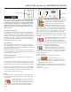
UNPACKING YOUR REFRIGERATOR Remove Packaging Your refrigerator has been packed for shipment with all parts that could be damaged by movement securely fastened. Cut the banding material at the bottom of the carton, unfold the carton at the bottom and remove the carton from the appliance. Remove the plastic bag, styrofoam corner posts and any tape holding the door closed and internal components in place.
INSTALLING YOUR REFRIGERATOR Select Location The proper location will ensure peak performance of your appliance. We recommend a location where the unit will be out of direct sunlight and away from heat sources. To assure your product performs to specifications the recommended installation location temperature range is from 65 to 90°F (18 to 32°C). Outdoor Installation Only the 3OARM & 6OARM models are suitable for outdoor installations.
USING YOUR MicroSentry™ REFRIGERATOR CONTROL Door Switch Control Figure 3 During initial startup, or anytime power is interrupted, there will be an approximate 5 minute delay before the refrigerator starts. During this period the controller will be assessing the temperature in the refrigerator and the display will appear erratic, this is normal. The desired temperature set point can be programmed during this start up period.
USING YOUR MicroSentry™ REFRIGERATOR CONTROL Alarm Mute Press any key to mute the audible portion of an alarm,. NOTE-This action will only mute the alarm. If the condition that caused the alarm continues, the alarm code will continue to flash and will sound for 20 seconds every 60 minutes. Turning Refrigerator Off To turn refrigerator off, press and hold “ON/OFF” button for three (3) seconds.
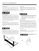
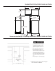
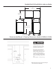
DIMENSIONS FOR MODELS 30ARM & 3OARM 37-5/32” (94.39 cm) 16-9/16” (42.06 cm) 25-7/32” (64.06 cm) 14-7/8” (37.78 cm) 23-9/32” (59.13 cm) 34-1/4” to 34-1/2” (87 to 87.6 cm) 3” to 3-1/4” 7.62 to 8.26cm) 21-3/16” (53.82 cm) Recommended Rough in Opening Dimensions, Models 30ARM & 3OARM Electrical Requirements: 115 volts, 3.3 amps running max. 15 amp dedicated circuit required. 3 prong grounded receptacle required. 34-1/2” (87.6 cm) *24” (61 cm) standard cabinet depth 15” (38.
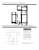
DIMENSIONS FOR MODELS 30ARM WITH OVERLAY DOOR 37-5/32” (94.39 cm) 23-1/4” (59.06 cm) 14-7/8” (37.78 cm) 22-17/32” (57.23 cm) 34-1/4” to 34-1/2” (87 to 87.6 cm) 3” to 3-1/4” 7.62 to 8.26cm) 21-3/16” (53.82 cm) Recommended Rough in Opening Dimensions, Model 30ARM Overlay Door Electrical Requirements: 115 volts, 3.3 amps running max. 15 amp dedicated circuit required. 3 prong grounded receptacle required. 34-1/2” (87.6 cm) *24” (61 cm) standard cabinet depth 15” (38.
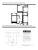
DIMENSIONS FOR MODELS 61ARM & 6OARM 47” (119.38 cm) 25-11/16” (65.28 cm) 26” (66.04 cm) 24-1/16” (61.11 cm) 23-7/8” (60.66 cm) 34-1/4” to 34-1/2” (87 to 87.6 cm) 3” to 3-1/4” 7.62 to 8.26cm) 22” (55.88 cm) Recommended Rough in Opening Dimensions, Models 6OARM & 61ARM Electrical Requirements: 115 volts, 3.3 amps running max. 15 amp dedicated circuit required. 3 prong grounded receptacle required. 34-1/2” (87.6 cm) Power outlet can be located in the back wall behind unit.
DIMENSIONS FOR MODEL 61ARM WITH OVERLAY DOOR 47” (119.38 cm) 24-1/16” (61.12 cm) 23-7/8” (60.66 cm) 23-5/16” (59.21 cm) 34-1/4” to 34-1/2” (87 to 87.6 cm) 3” to 3-1/4” 7.62 to 8.26cm) 22” (55.88 cm) Recommended Rough in Opening Dimensions, Model 61ARM Overlay Door Electrical Requirements: 115 volts, 3.3 amps running max. 15 amp dedicated circuit required. 3 prong grounded receptacle required. 34-1/2” (87.6 cm) Power outlet can be located in the back wall behind unit.
DIMENSIONS FOR MODEL 6ADAM 47” (119.38 cm) 25-11/16” (65.28 cm) 26” (66.04 cm) 23-7/8” (60.66 cm) 24-1/16” (61.11 cm) 31-5/8” to 31-7/8” (80.31 to 80.98 cm) 3” to 3-1/4” 7.62 to 8.26cm) 22” (55.88 cm) Recommended Rough In Opening Dimensions, Model 6ADAM Electrical Requirements: 115 volts, 3.3 amps running max. 15 amp dedicated circuit required. 3 prong grounded receptacle required. 32-1/2” (82.6 cm) Power outlet can be located in the back wall behind unit.
DIMENSIONS FOR MODEL 6ADAM WITH OVERLAY DOOR 47” (119.38 cm) 24-1/16” (61.12 cm) 23-5/16” (59.21 cm) 23-7/8” (60.66 cm) 31-5/8” to 31-7/8” (80.31 to 80.98 cm) 3” to 3-1/4” 7.62 to 8.26cm) 22” (55.88 cm) Recommended Rough In Opening Dimensions, Model 6ADAM Overlay Door Electrical Requirements: 115 volts, 3.3 amps running max. 15 amp dedicated circuit required. 3 prong grounded receptacle required. 32-1/2” (82.6 cm) Power outlet can be located in the back wall behind unit.
FULL OVERLAY PANEL INSTALLATION INSTRUCTIONS Step 1: Verify door alignment The door should be parallel to the sides and top of the refrigerator. If alignment is necessary the door may be adjusted by loosening the 2 screws which secure the hinge adapter brackets to the door and adjusting the door side to side. Use a 5/32” allen wrench for this procedure. (See Figure 3 below). Top hinge pin remove to remove the door.
FULL OVERLAY PANEL INSTALLATION INSTRUCTIONS Step 6: Drill holes in overlay panel Remove the hinge adapter bushings from the top and bottom door hinge adapters. (See Figure 8).Using the holes in the hinge adapters drill 5/16” (8mm) diameter clearance holes into the overlay panels 3/4” (20mm) deep. These will be clearance holes for the top and bottom hinge pins. Step 8: Assemble the lock parts Two (2) lock extensions are supplied with the lock.
FULL OVERLAY PANEL INSTALLATION INSTRUCTIONS Step 9: Secure overlay panel to the door. With the #8 wood screws provided fasten the overlay panel to the door. (See Figure 7). Step 10: Install lock cam (Models with locks only). Attach the lock cam to the back of the lock assembly with the phillips head machine screw provided. Orient the lock cam vertically when installing on the lock. Step 11: Install door gasket Press the door gasket into the door channel. Make certain the gasket corners are fully inserted.
CARE AND CLEANING Condenser Air Flow The machine compartment located beneath the cabinet does not require frequent cleaning; however, satisfactory performance depends on adequate ventilation. Be sure nothing obstructs the required air flow openings in front of the cabinet. At least once or twice a year, brush or vacuum lint and dirt from the front grille openings. See Figure 1 on page 3. Cabinet The painted cabinet can be washed with either a mild soap and water and thoroughly rinsed with clear water.
TROUBLESHOOTING YOUR REFRIGERATOR Before You Call for Service If the unit appears to be malfunctioning, read through this manual first. If the problem persists, check the troubleshooting guide below. Locate the problem in the guide and refer to the cause and its remedy before calling for service. The problem may be something very simple that can be solved without a service call. Some remedies listed in the Troubleshooting Guide are very complex.
HOUSEHOLD PRODUCT WARRANTY Entire Product Limited One Year Parts and Labor Warranty Marvel warrants that it will supply all necessary parts and labor to repair or replace in the end user’s home or office, any component which proves to be defective in material or workmanship, subject to the condition and exclusions stated below, for a period of one year from the date of purchase by the end user.
APPENDIX A, ADDITIONAL MicroSentry™ FEATURES Information Menu: The following features are available on the Information Menu. • Current Temperature • Maximum Stored Temperature • Minimum Stored Temperature • Total Operating Time Of The Condenser • Keypad Lockout To access the Information Menu Press “SET” button momentarily and release. Once in the information menu, the WARMER and COLDER keys may be used to scroll through the information menu.
www.marvelrefrigeration.com Northland-Marvel P.O. Box 400 1260 E. Van Deinse St. Greenville MI 48838 800.223.3900 41011753-EN Rev G 11/10/09 All specifications and product designs subject to change without notice. Such revisions do not entitle the buyer to corresponding changes, improvements, additions, replacements or compensation for previously purchased products.