OWNER’S GUIDE O WNERS G UIDE MAARRVVEELL UUN ND DEER RC CO OU UN NT TE ER R R M RE EF FR R II G G EE R RAT A TIIOONN FFOORR M # M MLC L RLE221254 MO OD DE EL L # T H E O R I G I N A L R E F R I G E R AT I O N E X P E RT S S I N C E 1 8 9 2 THE ORIGINAL REFRIGERATION EXPERTS SINCE 1892
WELCOME Welcome to the Marvel Experience Congratulations on your purchase of the industry’s quietest clear ice machine with the best ice clarity and purity. Your new investment is protected by a limited warranty for the first year, and hermetically sealed refrigeration system parts are covered for an additional 4 years. Here’s your guide to the operation and maintenance of your Marvel Clear Ice Machine to ensure years of enjoyment.
TABLE OF CONTENTS Tip: Click on any section below to jump directly there Safety Thermistor Important Safety Instructions Warranty Installation Unpacking Your Appliance Electrical Cutout & Product Dimensions Side-by-Side & Stacking Installations Integrated Panel Dimensions Integrated Panel Installation Installing The Water Supply Installing the Drain plumbing Maintenance Care and Cleaning Long-Term Storage/Winterization Operating Instructions Using Your Electronic Control Ice Maker Operation Service Obta
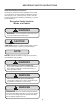
IMPORTANT SAFETY INSTRUCTIONS Important Safety Instructions Warnings and safety instructions appearing in this guide are not meant to cover all possible conditions and situations that may occur. Common sense, caution, and care must be exercised when installing, maintaining, or operating this appliance. Recognize Safety Symbols, Words, and Labels. ! WARNING WARNING - You can be killed or seriously injured if you do not follow these instructions.
UNPACKING YOUR APPLIANCE ! WARNING EXCESSIVE WEIGHT HAZARD Use two or more people to move product. Failure to do so can result in personal injury. Remove Interior Packaging Your appliance has been packed for shipment with all parts that could be damaged by movement securely fastened. Remove internal packing materials and any tape holding internal components in place. The owners manual is shipped inside the product in a plastic bag along with the warranty registration card, and other accessory items.
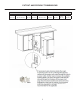
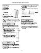
ELECTRICAL Electrical Connection A grounded 115 volt, 15 amp dedicated circuit is required. Do not remove ground prong This product is factory equipped with a power supply cord that has a three-pronged, grounded plug. It must be plugged into a mating grounding type receptacle in accordance with the National Electrical Code and applicable local codes and ordinances (see figure below).
CUTOUT AND PRODUCT DIMENSIONS ROUGH-IN OPENING DIMENSIONS "A" 15" (38.1 cm) CABINET DIMENSIONS "B" "C" "D" "E" 34" to 35" (86.4 to 88.9 cm) 24" (61 cm) 14 7/8" (37.8 cm) 3/4" "F" 3/4" 33 to 34 (84.5 to 87 cm) 7/8" 22 (58.1cm) "G" "H" "J" 3/ 38 /8" (98.7 cm) 17 1/2" (44.
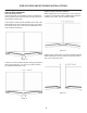
SIDE-BY-SIDE AND STACKING INSTALLATIONS Side-by-Side Installation Other Site Requirements Units must operate from separate, properly grounded electrical receptacles placed according to each unit's electrical specifications requirements. Hinge-by-Hinge Installation (Mullion) When installing two units hinge-by-hinge, 13/16" (22 mm) is required for integrated models. Additional space may be needed for any knobs, pulls or handles installed.
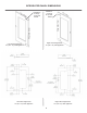
INTEGRATED PANEL DIMENSIONS do or Clearance for hinge at top and bottom Left Hand Hinged Door 15" (38.1 cm) wide appliance To p of do or Hinge side of door of Clearance for hinge at top and bottom Hinge side of door To p Right Hand Hinged Door 15" (38.1 cm) wide appliance 15⁄32" (2.9 cm) Left Hand Hinged Door 15" (38.1 cm) wide appliance Right Hand Hinged Door 15" (38.
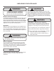
INTEGRATED PANEL INSTALLATION NOTE NOTE NOTE 10
USING YOUR ELECTRONIC CONTROL Electronic control Control Function Guide Function Command Notes ON/OFF Press and release. Unit will immediately turn ON or OFF. Enable Sabbath Mode Press and hold for 5 seconds and release. The oF / oC symbol will flash briefly after 5 seconds. Interior light and display will go dark and remain so until user resets mode - unit continues to operate. Disable Sabbath Mode Press and release. Display and interior light return to normal operation.
INSTALLING THE WATER SUPPLY Water Supply ! CAUTION Observe and follow all local building codes when installing this appliance. This ice machine must be connected to a potable cold water supply line. delivering water pressure between a minimum of 20 psi and a maximum of 120 psi. Use 1/4" copper tubing for your water supply which is available at any local hardware or plumbing supply store. Route the 1/4" copper tubing to suit your installation being sure not to kink the tubing.
INSTALLING THE DRAIN PLUMBING ! CAUTION Drain line coiled and secured to the back of the cabinet. Uncoil, route to an appropriate drain and cut to length. This drain pump is designed to be installed in Marvel ice machines only and approved for use with water only. ! WARNING Electrical Shock Hazard Risk of electrical shock or personal injury could occur due to moving components, if the machine compartment access cover is removed before unplugging the ice machine power cord. Drain pump vent tube.
ICE MAKER OPERATION The Ice Making Process fractional freezing to form a slab of ice that is clear and has less dissolved solids than the water it is produced from. This is accomplished by running water over the cold evaporator plate which gradually freezes leaving the dissolved solids in the residual reservoir water to provide clear ice. Water distributor sheet is released and slides onto the grid cutter cutter’s heated wires.
ICE MAKER OPERATION The ice machine will keep producing ice until the ice machine’s bin is full and will restart automatically when ice needs to be replenished in the bin. The ice bin is machine to run for 24-48 hours to accumulate ice in the ice machine’s bin. Ice Production In normal mode the ice machine will produce up to 39 pounds (17.7 kg) of clear ice in a 24-hour period when installed in a 72°F ambient with a 55°F water supply.
CLEANING YOUR ICE MACHINE Clean reminder: CLEAN When cleaning is needed, UI will alternate between "CL" and "ICE" every 3000 cycles to indicate that the unit needs to be cleaned. Over time, mineral buildup on the cold evaporator plate can occur which can adversely affect the quality of your ice. This build-up is dependent on your water source and usage. Normal ice production will continue while the "CLEAN" reminder is displayed.
LONG TERM STORAGE AND WINTERIZATION water in the ice-making system. ! CAUTION This ice machine must have all water drained and removed to prevent ice machine damage as well as possible water damage to the surrounding area in freezing conditions. These damages are not covered under warranty. ! CAUTION Do not use any type of anti-freeze or other solution as a substitution for properly draining the ice machine.
LONG TERM STORAGE AND WINTERIZATION 7. Disconnect the water valve’s outlet water line to the reservoir and drain the remaining water left in the water line trap area. Reconnect the water valve outlet water line. Reinstall the ice machine’s access cover. Clean and dry the ice machine’s storage bin. Prop the door open for air circulation to prevent mold and mildew. Leave the water supply line disconnected or reconnect water on and allow water to enter back into the water valve.
LONG TERM STORAGE AND WINTERIZATION To Restart the Ice Machine access for the air hose. Apply air pressure (approximately 10 psi) to the end of the vent tube which will purge the remainder of the water from the drain pump and the drain line. Reinstall the vent tube and clamp to the back of the ice machine and remove the winterization plug from the ice bin and save it for future use. Reconnect or turn on the water supply line. Reconnect drain tubing if removed.
OBTAINING SERVICE If Service is Required: • If the product is within the first year warranty period please contact your dealer or call Marvel Customer Service at 616.754.5601 for directions on how to obtain warranty coverage in your area. • If the product is outside the first year warranty period, Marvel Customer Service can provide recommendations of service centers in your area. A listing of authorized service centers is also available at www.marvelrefrigeration.
TROUBLESHOOTING Before You Call for Service troubleshooting guide below. Locate the problem in the guide and refer to the cause and its remedy before calling for service. The problem may be something very simple technician. ! WARNING Electrocution Hazard • Never attempt to repair or perform maintenance on the appliance until the main electrical power has been disconnected. Turning the appliance control "OFF" does not remove electrical power from the unit's wiring.
TROUBLESHOOTING Troubleshooting the Drain Pump Ice Quality Is there mineral scale build up on the evaporator plate NOTE If the drain pump reservoir (not the ice machine bin) Is there a high mineral content in the water? The water Are food items being stored in the ice bin? Remove food from the ice bin. Unpleasant Odors on the water supply line. Clumps of ice Are there clumps of ice in the bin? If the ice isn’t used on a regular basis it will melt and form into clumps.
Product Liability Field service technicians are authorized to make an initial assessment in the event of reported damages. If there are any questions about the process involved, the technician should call Marvel for further explanation. While inspecting for defects or installation issues, photos should be taken to document any damages or issues found.
Warranty Claims Units must be registered prior to warranty submittal. The following information defines the parameters for filing a warranty claim: com. A proof of purchase is required. We also accept the following information to update warranty: • Valid serial number needed • Valid model number needed • Claims must be submitted online at www. marvelservice.
Ordering Replacement Parts Parts may be o rdered online at partsformarvel.com Or contact: www.marvelrefrigeration.com (Servicers choose "Login" for service account). Phone Numb er: (616) 754-5601 NOTICE Use only genuine Marvel replacement parts. The use of non-Marvel parts can reduce performance, damage the unit, and void the warranty. Warranty parts will be shipped at no charge after Marvel confirms warranty status. Please provide the model, serial number, part number and part description.
R-600A Specifications & Handling Gloves and Eye Protection must be used. ,., . ���· ' R-600a is considered non-toxic, but is flammable when mixed with air. Keep a dry powder type fire extinguisher in the work area. R-600a is heavier than air, do not allow any leakage/migration to low areas such as basements and stairs. RISK Of FIRE OR EXPLOSION. FLAMMABLE REFRIGERANT USED. TO BE REPAIRED ONLY BY TRAINED SERVICE PERSONNEL DO HOT PUNCTURE REFRIGERANT TUBING RISK Of FIRE OR EXPLOSION.
IA WARNING I Only skilled and well trained service technicians permitted to service R-600a equipped products. R-600A SPECIFICATIONS/LABELING R-600a equipped products are labeled (both the unit and the compressor). R-600a is colorless and odorless. All tools and equipment must be approved for use with R-600a refrigerant. R-600a is considered non-toxic, but is flammable when mixed with air. Local, state and federal laws, standards must be observed along with proper certification and licensing.
Evacuate/reclaim via the piecing pliers to ensure the When re-brazing, the system must be purged with dry system is empty of R-600a before any system work is nitrogen and at least one access point open to the performed. atmosphere. When re-brazing, proper ventilation is required along with constant monitoring for the presence of R600a refrigerant. GAS LEAi< The filter dryer must be replaced any time the sealed system is serviced.
The low side of the refrigeration system (evaporator, Proper ventilation during service is required. compressor and suction line) must be leak tested with the compressor off (equalized pressure). Never apply a torch to a charged R-600a refrigeration system. RECHARGING No air is ever to be allowed inside the refrigeration system (R-600a refrigerant or dry nitrogen only). Use OEM replacement service parts and do not alter the construction of the unit.
System Diagnosis Guide REGRIGERATION SYSTEM DIAGNOSIS GUIDE Capillary Tube Evaporator Wattage Very hot Warm Cold Normal Slightly warm to hot Hot to warm Cool Cold Higher than normal Hot Warm Warm Extremely cold near inlet - Outlet below room temperature Lower than normal Somewhat Warmlower than near room normal vacuum temperature Very hot Top passes Room temperature warm Lower (cool) or colder passes cool (near room temperature) due to liquid Extremely cold near inlet - Outlet below room
Compressor Specifications A DANGER Electrocution can cause death or serious injury. Burns from hot or cold surfaces can cause serious injury. Take precautions when servicing this unit. Disconnect the power source. FMXA9C REFRIGERANT R600A VOLTAGE 115 VAC FREQUENCY 60 Hz START WINDING 5 Ohm at 77° F RUN WINDING 7 Ohm at 77° F RUN TO START 12 Ohm at 77° F LRA 8.0 A FLA 2.18 A STARTING DEVICE Do not stand in standing water when working around electrical appliances.
MODEL LIST Model # Model 29 *HKR524-***1A 67 MPFZ424, MOFZ224, MLFZ224 30 *HKR524-***2A 31 *HWC315-***2A 68 MPBV424, MPRE424 32 *HWC315-***1A 69 MPWC424 33 *HWC318-***1A 70 MPDR424, MODR224 34 *HWC324-***2A 71 MPBV415 35 *HWC324-***1A 72 MPWC424, MPWC415 36 *HWC515-***2A 73 MPRF424, MPRI424, MLRF224,MLRI224,MORF224 37 *HWC515-***1A 38 *HWC524-***1A 74 MPWD424, MLWD224 39 *HWC524-***2A 75 MPWD424, MLWD224 40 *HWC336-***1A 41 *HBD324-***1A 42 *HBD324-***2A 43 *
Comp/Fan Compressor Compressor Clear Ice, 3 Class **BV315-***1A 01 Control Operation-Service 33 Compressor Compressor Compressor **WD524-***1A **RF124-***1A **RI124-***1A 46 48 52 50 Compressor Compressor **BD524-***1A **WD324-***1A 43 Compressor Compressor **WC336-***1A **BD324-***1A 40 Compressor **WC524-***1A 37 38 41 Compressor Compressor Compressor **WC318-***1A 33 **WC324-***1A Compressor **WC315-***1A 32 **WC515-***1A Compressor **KR524-***1A 27 29 35 Compress
Thermistors Evaporator Thermistor Thermistors are used for various temperature readings. If the evaporator thermistor fails, the unit will rely on a Thermistors provid e reliable temperature readings preset defrost timer during defrost cycles. The unit will using a resistance which varies based on surrounding otherwise operate normally. Refer to defrost section. temperatures. If a faulty thermistor is suspected it may be tested using an accurate ohmmeter.
HOUSEHOLD PRODUCT WARRANTY Marvel Refrigeration (Marvel) Limited Warranty ONE YEAR LIMITED PARTS & LABOR WARRANTY For one year from the date of original purchase, this warranty covers all parts and labor to repair or replace any part of the product that proves to be defective in materials or workmanship. For products installed and used for normal residential use, material cosmetic defects are included in this warranty, with coverage limited to 60 days from the date of original purchase.
www.marvelrefrigeration.com Marvel Refrigeration 1260 E. Van Deinse St. Greenville MI 48838 616.754.5601 All specifications and product designs subject to change without notice. Such revisions do not entitle the buyer to corresponding changes, improvements, additions, replacements or compensation for previously purchased products.