
Operating instructions


6 Masport I43 NEW YORK / ULTIMATE Gas Inbuilt Fireplace
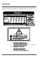
INSTALLATION CHECKLIST
The Masport Gas Inbuilt is installed as listed below.
1) Unit Location - check Clearances to Combustibles on
page 7.
2) Make the gas connections and electrical connection for
fan and flue spill switch. See page 8.
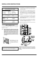
3) Install the flue or liner to the sliding draft diverter. See
page 9.
4) Install Flueing, page 9. Slide the unit into the fireplace and
level. Attach draft diverter to the inbuilt.
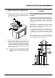
5) Test gas pressure, page 10. Check aeration, page 10.
6) Test for flue spillage, page 11.
7) Assemble and install the faceplate and trim. See page 12.
8) Install the optional brick panels. See page 13.
9) Install the 3 logs and embers. See page 13.
10) Install Doors. See page 14.
11) Install Optional Remote Control and Optional Wall Ther-
mostat, pages 14 and 15.
12) Explain controls to the homeowner.
13) Final check: Before leaving this unit with the customer,
the installer must ensure that the appliance is firing
correctly. This includes:
a) Clocking the appliance to ensure the correct firing
rate.
b) Adjusting the primary air, if required, to ensure that
the flame does not carbon. See page 10.
c) Ensuring that the appliance is flueing correctly. See
page 11.
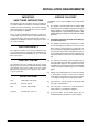
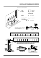
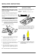
MATERIALS REQUIRED
No electrical power supply is required for the gas control to
operate. A 240 Volt AC power cord is hooked up to the fan
switch and fan. Plug 3 wire cord into a suitable receptacle. Do
not cut the ground terminal off under any circumstances.
When connected with 240 volts, the appliance must be
electrically grounded in accordance with local codes, or in the
absence of local codes with the current version of National
Code AS 3100.
INSTALLATION REQUIREMENTS
Note: This unit is equipped with a heat sensor thermo-
disc which will prevent the fan from operating until
the unit reaches the correct temperature.
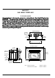
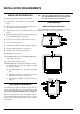
CLEARANCES
Minimum Fireplace Clearances
The minimum fireplace clearances for the Masport gas inbuilt
fireplace are shown in the following diagrams: