Owners & Installation In-built Fireplaces Ontario / Vancouver Manual Model: I2101 Model: I3101 PLEASE KEEP THESE INSTRUCTIONS FOR FUTURE REFERENCE Head Office - Australia 54 Boundary Rd. Braeside P.O. Box 553 Mordialloc 3195 Ph. (03) 9586-7777 Fax. (03) 9586-2980 Head Office - New Zealand 1-37 Mt Wellington Hwy.Panmure, P.O. Box 14349 Auckland 6. Ph. (9) 570-9009 Fax.
Thank-you for purchasing a MASPORT FIREPLACE PRODUCT. The pride of workmanship that goes into each of our products will give you years of trouble-free enjoyment. Should you have any questions about your product that are not covered in this manual, please contact the MASPORT DEALER in your area. Keep those MASPORT FIRES burning. SAFETY NOTE: If this in-built fireplace is not properly installed, a house fire may result.
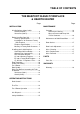
TABLE OF CONTENTS THE MASPORT IN-BUILT FIREPLACE & HEARTH HEATER Page INSTALLATION In-built fireplace Safety Labels Ontario (I2101M) ................................ 4 Vancouver (I3101L) ............................ 5 Before Installing Your Unit ....................... 6 Chimney Specifications ...................... 6 Installation in "0" Clearance Factory Built Fireplace ................................. 6 Fireplace Specifications ..................... 6 Masonry & Factory Built Clearances ..
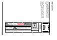
C D E G INSTALL ONLY ON A NON-COMBUSTIBLE HEARTH RAISED (F) 1.5IN / 38MM ABOVE AN ADJACENT COMBUSTIBLE FLOOR. COMBUSTIBLE FLOOR MUST BE PROTECTED BY NON-COMBUSTIBLE MATERIAL EXTENDING (E) 16 IN / 405 MM TO FRONT AND (G) 8 IN / 205 MM TO SIDES FROM FUEL DOOR. F COMPONENTS REQUIRED FOR INSTALLATION: 6IN / 150MM STAINLESS STEEL LINER. OPTIONAL COMPONENT: FAN, ELECTRICAL RATING: VOLTS 115, 60 HZ, 0.6 AMPS DO NOT REMOVE BRICKS OR MORTAR IN MASONRY FIREPLACE. FOR USE WITH SOLID WOOD FUEL ONLY.
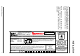
106 This is a copy of the label that accompanies each Vancouver In-built Fireplace. We have printed a copy of the contents here for your review. NOTE: Masport units are constantly being improved. Check the label on the unit and if there is a difference, the label on the unit is the correct one. Masport In-built Fireplaces DO NOT REMOVE THIS LABEL LISTED FACTORY BUILT FIREPLACE INSERT CERTIFIED FOR USE IN CANADA AND U.S.A. MODEL: I3100L TESTED TO: ULC S628-M91 / UL 1482-1991 REPORT NO. 632-323500 (MAR.
INSTALLATION Masport In-built Fireplaces are constructed with the highest quality materials and assembled under strict quality control procedures that insure years of trouble free and reliable performance. It is important that you read this manual thoroughly and fully understand the safe installation and operating procedures. The more you understand the way your Masport In-built Fireplace operates, the more enjoyment you will experience from knowing that your unit is operating at peak performance.
INSTALLATION Masonry and Factory Built Fireplace Clearances The minimum required clearances to combustible materials when installed into a masonry or factory built fireplace are listed below. Unit Adjacent Side Wall (to Side) A Mantle (to Top) B Top Facing (to Top) C Side Facing (to Side) D Minimum Hearth Extension* E Minimum Hearth Elevation* F Minimum Hearth Side Extension G Ontario In-built (I2101M) 10"/530mm 17"/430mm 10.25"/260mm 8"/203mm 16"/406mm 1.
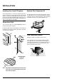
INSTALLATION Installing Your In-built Fireplace Optional Flue Connector Kit Your in-built fireplace is very heavy and will require two or three people to move it into position. The in-built fireplace can be made a little lighter by removing the cast iron door by opening it and lifting it off its hinges. Be sure to protect your hearth extension with a heavy blanket or carpet scrap during the installation.
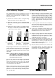
INSTALLATION A) Into a Masonry Fireplace B) Into a Factory Built Fireplace The in-built fireplace must be installed as per the requirements of your local inspection authority. Three methods of flue connection are acceptable in most areas, these include: 1) When installed in a factory built fireplace, a full stainless steel rigid or flexible flue liner is mandatory, for both safety and performance purposes.
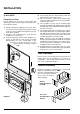
INSTALLATION C) ALL UNITS Faceplate and Trim Prior to sliding your insert into its final position and attaching the connector or liner pipe, the faceplate must be installed as follows: 1) Slide the spring nuts (supplied) over the slots in the insert’s side convection panels (the spring nuts may need to be squeezed with a pair of pliers first, to help them stay in position). 2) Screw the side faceplate panels, (item A in the diagram) one to each side.
INSTALLATION Fan/Blower Your fan should only be installed once the unit is in place in order to prevent any damage to the fan. To attach, follow the instructions provided with the fan. Make sure to install the rubber grommet to the fan housing before it is installed on the insert. 1) Remove the protective covering from the brass trim on the fan. 2) Align the fan support with the offset clip on the bottom of the ashlip. 3) Slide the supports into the clips.
INSTALLATION Brick Flue Baffle & Secondary Air Tube Installation The flue baffle system located in the upper area of the firebox is removable to make cleaning your chimney system easier. The brick baffles must be installed prior to your first fire. Smoke spillage and draft problems may occur if the baffles are improperly positioned. Check the position of the brick baffles on a regular basis as they can be dislodged if too much fuel is forced into the firebox.
INSTALLATION Ontario In-built Fireplace (I2101M) The unit arrives with the 2 baffle bricks on the floor of the firebox. 1) If all 3 air tubes are installed continue on to Step 2), if not, follow the instructions below. Install the air tube into the holes in the side channels. The notch goes on the right hand side with the air holes facing toward the door. Slide the tube into the left hand side, as far as possible and then bring it back into the hole on the right hand side until it locks into position.
OPERATING INSTRUCTIONS First Fire When your installation is completed and inspected, you are ready for your first fire. 1) Open draft control fully. 2) Open firebox door and build a small fire using paper and dry kindling, wait a few minutes for a good updraft in the flue to establish the fire. Leaving the door slightly open will help your fire start more rapidly. 9) During the first few hours it may be more difficult to start the fire.
OPERATING INSTRUCTIONS Fan Operation Some Safety Guidelines The fan is to be operated only with the draft control rod pulled out at least 1/2"(13mm) from the fully closed position. The fan is not to be operated when the draft control rod is in the closed position (pushed in). The fully closed position is the low burn setting. 1) Never use gasoline, gasoline type lantern fuels, kerosene, charcoal lighter fuel, or similar liquids to start or ‘freshen up’ a fire in your heater.
MAINTENANCE 2) Call the Fire Department 13) Do not store any fuel closer than 2 feet from your unit. Ways to Prevent and 14) Do not burn salt drift wood as it will corrode your unit Keep Unit Free of Creosote and void the warranty. 15) Do not operate the unit if the glass is broken or missing. Do not operate the unit if the gasketing is worn out and not sealing the door or the glass.
MAINTENANCE use and at least once a year thereafter or when needed. Maintenance of Gold-Plated Doors The gold electroplated finish on the doors requires little maintenance, and need only be cleaned with a damp cloth. DO NOT use abrasive materials or chemical cleaners, as they may harm the finish and void the warranty. Door Gasket If the door gasket requires replacement, 7/8" diameter material must be used. A proper high temperature gasket adhesive is required.
REPLACEMENT / SPARE PARTS LIST Ontario - Medium Inbuilt Fireplace I2101 - Main Assembly 2) 4) 5) 6) 7) 9) 16) 17) 19) 20) 23 Part # Part # Description Australia New Zealand 846-916 Large Door Assy - Black 846-910 Large Door Assy - Gold 846-304 Glass - Large 936-243 560087 7/8" Glass Gasket 846-920 560202 Glass Retainer Clips (Set) * Screw - 1/4 - 20 x 3/8" 948-172/P Large Glass Retainer 846-973 Door Handle Assembly 846-570 560203 Door Gasket Kit 846-918 560204 Hinge Cap - Gold (2/set) 948-101 560208 Sprin
REPLACEMENT / SPARE PARTS LIST Ontario - Medium Inbuilt Fireplace I2101 - Accessories Part # Australia Part # Description New Zealand 70) 902-111 76) 802-152 78) 802-143 Bricks Brick: 32mm x 114mm x 229mm Brick: 32mm x 51mm x 229mm Brick: 32mm x 57mm x 57mm 140-911 285) 143-161 286) 143-158 287) 143-160 288) * 289) * Faceplate & Trim - Regular Trim - Right - Regular Trim - Top - Regular Trim - Left - Regular Faceplate - Side - Regular Faceplate - Top - Regular 140-913 295) 143-164 296) 143-162 297) 14
REPLACEMENT / SPARE PARTS LIST Vancouver - Large Inbuilt Fireplace I3101 - Main Assembly Part # Australia 1) 3) 4) 5) 6) 7) 9) 16) 17) 19) 20) 23) 35) 36) 38) 846-916 846-910 846-304 936-243 846-920 * 948-172/P 846-973 846-570 846-918 948-101 948-102 820-235 063-954 063-953 063-955 42) 163-930 163-932 43) * 44) * 45) * 20 Part # Description New Zealand 560087 560202 560203 560204 560208 Large Door Assy - Black Large Door Assy - Gold Glass - Large 7/8" Glass Gasket Glass Retainer Clips (set) Screw - 1
REPLACEMENT / SPARE PARTS LIST Vancouver - Large Inbuilt Fireplace I3101 - Accessories Part # Australia Part # Description New Zealand 70) 902-111 71) 802-104 72) 802-146 Bricks Brick: 32mm x 114mm x 229mm Brick: 32mm x 102mm x 229mm Brick: 32mm x 45mm x 229mm 163-910 385) 163-165 386) 163-160 387) 163-161 388) * 389) * Faceplate & Trim - Regular Trim - Right - Regular Trim - Top - Regular Trim - Left - Regular Faceplate - Side - Regular Faceplate - Top - Regular 163-912 395) 163-164 396) 163-162 397)
NOTES 22 Masport In-built Fireplaces
WARRANTY The Masport Express Warranty for Woodfires and Pot Belly Stoves Important: For all Masport Woodfires and Pot Belly Stoves, please read the Owner Manual and this Express Warranty before using the product. This Express Warranty does not cover damage due to misuse or failure to follow the operating and installation instructions.