How to use this file...(Operators Manuals) ————————————————————————————————————————————––– Instructions for Print Vendors (Paper Manuals) Paper Size: * 11 x 17 * Body—50 lbs brilliant white offset or equivalent. * Cover—on pre-printed two-tone “Swash” stock. Press: * Body—1-color, 2-sided * Cover imprint —1-color, 1-sided Bindery: * Saddle Stitch, Face Trim * Face Trim COVERS: * This file contains several manuals, which differ only in their covers.
THIS PAGE INTENTIONALLY BLANK
OPERATOR’S MANUAL Sovereign Series 18HP Hydro Tractors 48” Mower Decks Mfg. No. 1692450 1692796 1692798 1692889 1692943 1692945 1693144 1693146 1693148 1693407 1693409 Mfg. No. 1691219 1692890 1693173 1693418 Description Sovereign, 18HP Hydro Sovereign, 18HP Hydro Sovereign, 18HP Hydro w/ PS Sovereign, 75th Anv. 18HP Hydro Sovereign, 18HP Hydro w/ PS Sovereign, 18HP Hydro Sovereign, 18HP Hydro Sovereign, 18HP Hydro w/ PS Sovereign, 75th Anv. 18HP (Ex.
MANUFACTURING, INC. 500 N Spring Street / PO Box 997 Port Washington, WI 53074-0997 www.simplicitymfg.com © Copyright 2002 Simplicity Manufacturing, Inc. All Rights Reserved. Printed in USA.
OPERATOR’S MANUAL 900 Series 18HP Hydro Tractors 48” Mower Decks Mfg. No. 1692452 1692845 1692847 1692949 1692951 1693411 1693413 Mfg. No.
AGCO-Allis Lawn & Garden Equipment 500 N. Spring Street \ P.O. Box 997 Port Washington, WI 53074-0997 USA www.allislawn.com © Copyright 2002 Simplicity Manufacturing, Inc. All Rights Reserved. Printed in USA.
OPERATOR’S MANUAL 2800 Series 18HP Hydro Tractors 48” Mower Decks Mfg. No. 1692503 1692849 1692852 1692953 1692955 1693415 1693417 Mfg. No.
Massey Ferguson Lawn & Garden Equipment is Manufactured and Distributed by Simplicity Manufacturing, Inc. 500 N. Spring Street • P.O. Box 997 • Port Washington, WI 53074-0997 USA www.masseylawn.com © Copyright 2002 Simplicity Manufacturing, Inc. All Rights Reserved. Printed in USA.
Table Of Contents TRACTOR & MOWER IDENTIFICATION .....................2 BATTERY SERVICE....................................................20 Checking Battery Voltage ...................................................20 Charging A Completely Discharged Battery .......................20 Jump Starting with an Auxiliary Battery ..............................20 SAFETY RULES ............................................................3 SAFETY DECALS .........................................................
Tractor & Mower Identification IDENTIFICATION TAG LOCATIONS When contacting your Authorized Dealer for replacement parts, service, or information YOU MUST HAVE THESE NUMBERS. SA Simplicity Manufacturing, Inc. MP Port Washington, WI 53074-0997 U.S.A. MFG 169XXXX SERIAL LE Mower Identification Tag Tractor Identification Tag XXXXX Figure 1.
Safety Rules Read these safety rules and follow them closely. Failure to obey these rules could result in loss of control of rider, severe personal injury or death to you, or bystanders, or damage to property or equipment. This mowing deck is capable of amputating hands and feet and throwing objects. The triangle in text signifies important cautions or warnings which must be followed. GENERAL OPERATION WARNING - SLOPE OPERATION Never operate on slopes greater than 30 percent (16.
Safety Rules CHILDREN SERVICE AND MAINTENANCE Tragic accidents can occur if the operator is not alert to the presence of children. Children are often attracted to the unit and the mowing activity. Never assume that children will remain where you last saw them. • Use extra care in handling gasoline and other fuels. They are flammable and vapors are explosive. a) Use only an approved container. b) Never remove gas cap or add fuel with the engine running. Allow engine to cool before refueling. Do not smoke.
Safety Decals This unit has been designed and manufactured to provide you with the safety and reliability you would expect from an industry leader in outdoor power equipment manufacturing. All WARNING, CAUTION and instructional messages on your tractor and mower should be carefully read and obeyed. Personal bodily injury can result when these instructions are not followed. The information is for your safety and it is important! The safety decals shown below are on your tractor and mower.
Features & Controls TRACTOR CONTROLS *2240 Figure 2. Tractor Controls REF A NAME Gasoline Gauge FUNCTION Shows gasoline level and serves as a tank cap B Ammeter Shows when battery is being charged or discharged. C Clutch/Brake Pedal Disengages clutch when depressed at least halfway. Applies brake when fully depressed. D Ground Speed Control Lever Controls forward and reverse ground speeds. E Ignition Switch & Key Starts and stops engine.
Features & Controls SAFETY INTERLOCK SYSTEM *2293 Your tractor is equipped with a seat switch safety system that will automatically shut the engine off when the operator leaves the seat with the ground speed control lever in gear or with the PTO engaged. Once the engine has stopped, the electric PTO switch must be turned off after operator returns to the seat in order to start the engine.
Operation GENERAL Before operating this tractor for the first time, the owner should operate in an open area without mowing, to become accustomed to the unit. The right side of the mower can be used to trim close to objects. Be sure to read all information in the Safety and Operation sections before attempting to operate this tractor and mower. CAUTION Towing the tractor will cause transmission damage. Do not use another vehicle to push or pull tractor.
Operation STOPPING THE TRACTOR Refer to figure 2. 1. Move ground speed control lever (D) to neutral and depress brake pedal. 2. Switch PTO to off. 3. Move throttle midway between slow and fast position before shutting off engine. 4. To set parking brake depress brake pedal and pull parking brake lever (F) up. 5. Push hydraulic lift lever forward to lower attachment. 6. Turn ignition off and remove key to prevent unauthorized use.
Operation A. B. C. D. E. F. G. H. I. J. K. L. M. PTO Clutch Lever PTO Drive Pulley Belt Tensioning Lever Mower Drive Belt Lift Anchor Lift Cable Clevis Deflector Mower Drive Pulley Mower Hitch Arm Tractor Front Hitch Lift Lever Front Idler Pulley Rear Idler Pulley *2248 Figure 4. Mower Installation & Removal MOWER INSTALLATION *2249 WARNING It will be necessary to start the engine to raise or lower the lift cable. Before starting the engine, always seat yourself in the operator’s position.
Operation 5. Slide the mower under the tractor, then turn the front wheels to face straight ahead. Use the lift cable pin and spring clip to attach the tractor lift cable clevis (F,) to the mower lift anchor (E). Use the lower hole on top lift cable clevis (not shown) for a higher transport position. MOWER REMOVAL 6. Start the engine and raise the mower halfway using the lift lever. Be sure to shut off tractor engine before leaving the seat. 1.
Normal Care SCHEDULE The following schedule should be followed for normal care of your tractor and mower. You will need to keep a record of your operating time. See Page 7 Every 100 Hours *Or Yearly ● Check tractor brakes. 24 ● Normal Care Items Check tractor & mower for loose hardware. – Lubricate tractor and mower. - ● Check tires. 13 ● Oil Pivot points. 15 ● Check transmission fluid. 15 Change transmission fluid & filter. 16 Check and clean battery.
Normal Care LUBRICATION *2242 Tractor Lubrication Lubricate the tractor as shown in figures 8 -10. When a grease gun is shown, wipe the fitting clean, apply two or three shots of lithium base automotive grease, and wipe off excess grease. When an oil can is shown, wipe the area clean, apply a few drops of oil (SAE 30), then wipe up drips or spills. Mower Lubrication Figure 8. Clutch/Brake Pedal Grease Fitting 1. Remove mower from tractor. 2. Remove cotter pins in order to lift the bail assembly.
Normal Care *1606 *313 Figure 12. Mower Arbor *2245 Figure 11. Idler Pulley Pivot A. Cover C. Bail Assembly B. Taptite Screws D. Idler Pulley Pivot Figure 13. Bevel Gear Box A. Oil Fill/Check Plug B. Bevel Gear Box *310 CHANGING TRANSMISSION FLUID & FILTER NOTE: The filter is shown in figure 14. Replace the filter every 400 hours of operation or whenever changing transmission fluid.
Normal Care 5. When fluid has drained out of transmission, install new filter. Coat gasket on filter with transmission fluid. Screw filter on until it contacts base, then tighten 1/2 - 3/4 turn more. Do not use any tools to tighten filter. Turn by hand only. *2247 6. Install and tighten drain plug. 7. Remove the fill cap (C, figure 14) and clean dirt away from relief valve (E).
Normal Care Thin Finishing Nail Figure 18 Balancing The Blade LOOSEN B C Figure 17. Removing The Blade SERVICING THE MOWER BLADES 1. Remove mower from the tractor. 2. Blades should be sharp and free of nicks and dents. If not, sharpen blades as described in following steps. D A 3. To remove blade for sharpening, use wooden block to hold blade while removing the blade mounting capscrew (figure 17). 4. Use a file to sharpen blade to fine edge. Remove all nicks and dents in blade edge.
Storage STORAGE WARNING Temporary Storage (30 Days Or Less) Never store the unit, with gasoline in engine or fuel tank, in a heated shelter or in enclosed, poorly ventilated enclosures. Gasoline fumes may reach an open flame, spark or pilot light (such as a furnace, water heater, clothes dryer, etc.) and cause an explosion. Remember, the fuel tank will still contain some gasoline, so never store the unit indoors or in any other area where fuel vapor could travel to any ignition source.
Troubleshooting & Repair Engine starts hard or runs poorly. GENERAL 1. Fuel mixture too rich. Clean air filter. Check choke adjustment (engine speed control). See engine manual. WARNING To avoid serious injury, perform maintenance on the tractor or mower only when the engine is stopped and the parking brake engaged. Always remove the ignition key, disconnect spark plug wire and fasten away from the plug before beginning the maintenance, to prevent accidental starting of the engine. 2.
Troubleshooting & Repair Brake will not hold. Excessive mower vibration. 1. Brake is incorrectly adjusted. See Brake Adjustment. 2. Brake lining worn. Replace. 1. Blade mounting screws are loose. Tighten to 50-70 ft.lbs. (74 Nm.). Engine backfires when shut off. 2. Mower blades, arbors, or pulleys are bent. Check and replace as necessary. 1. Engine backfire may occur when shut off hot. To reduce backfiring, move throttle lever midway between fast and slow for a couple seconds before shut off. 3.
Troubleshooting & Repair BATTERY SERVICE 6. Charge the battery until fully charged (i.e. until the specific gravity of the electrolyte is 1.250 or higher and the electrolyte temperature is at least 60° F). The best method of making certain a battery is fully charged, but not over charged, is to measure the specific gravity of a cell once per hour. The battery is fully charged when the cells are gassing freely at low charging rate and less than 0.
Troubleshooting & Repair THIS HOOK-UP FOR NEGATIVE GROUND VEHICLES To Starter Switch To Starter Switch Jumper Cable Starting Vehicle Battery Discharged Vehicle Battery Jumper Cable To Ground Engine Block MAKE CERTAIN VEHICLES DO NOT TOUCH Figure 20.
Adjustments 1972_SVr1 WARNING To avoid serious injury, perform adjustments only with engine stopped, key removed and tractor on level ground. SEAT ADJUSTMENT Lever SEAT-SLIDE EQUIPPED MODELS For units equipped with a Seat Slide, See Figure 21. Use the lever under the front of the seat to adjust the seat forward or rearward for best rider comfort. STANDARD MODELS 1. See Figure 22. Lift up the seat and loosen the four capscrews. Figure 21 Seat Adjustment *2293 Springs 2.
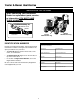
Adjustments A. Hydrostatic Control Lever B. Parking Brake Handle C. Fender D. Parking Brake Rod End E. Jam Nut F. Parking Brake Rod G. Foot Brake Rod Guide H. Jam Nuts I. Foot Brake Rod J. Jam Nuts K. Clutch Rod Guide L. Clutch Rod **256 Figure 24. Clutch/Brake Adjustment CLUTCH/BRAKE ADJUSTMENT See Figure 24. 1. Engage the parking parking brake. Adjust jam nuts (H) on end of foot brake rod to provide 1/2” (12.7 mm) spring length between washers. 2. Depress the pedal to engage the brake.
Adjustments WARNING Before checking mower, shut off PTO and engine. Allow all moving parts to stop. Remove ignition key, then disconnect the spark plug wire and fasten it away from the spark plug. 4. Stop the engine, set the parking brake and raise the seat deck. Loosen the jam nut (H) on end of cam pivot shaft (G). If tractor creep had been in reverse, turn adjusting nut (I) 1/8 - 1/4 turn clockwise when viewed from right side of tractor.
Belt Replacement *2247 CAUTION To avoid damaging belts, do not pry belts over pulleys. TRACTOR DRIVE BELT See Figure 27. 1. Park the tractor on a smooth, level surface such as a concrete floor. Disengage the PTO, turn off the engine and lock the parking brake. Remove the key. 2. Tie the clutch/brake pedal down in the disengaged position. 3. Raise the tractor seat deck. Remove the capscrew (C) and belt guard assembly (B). 4.
Specifications NOTE: Specifications are correct at time of printing and are subject to change without notice. ENGINE TRANSMISSION Type Pump Motor Hydraulic Fluid 18 HP Kohler OHC Model Horsepower Cylinders Bore Stroke Displacement Construction Electrical System Ignition Governor Air Cleaner Lubrication Oil Capacity Fuel Tank Muffler Kohler OHC Overhead Cam, TH18S 18 HP @ 3600 rpm 2 3.03 In. (77 mm) 2.64 In. (67 mm) 35 Cu. In.
Parts & Accessories COMMON REPLACEMENT PARTS MAINTENANCE ITEMS Listed below are the more common replacement parts. Only genuine factory replacement parts will assure optimum performance and safety. Do not attempt repairs or maintenance unless proper procedures and safety precautions are followed. For assistance in any area, see your dealer. • Simplicity Engine Oils Case of 12 qts. (Your dealer has 1 qt.
Parts & Accessories OPTIONAL ACCESSORIES See your dealer to purchase these items.