ITEM #0503215 4-BURNER GRILL WITH SIDE BURNER Master Forge & M Design® is a registered trademark of LF, LLC. All rights reserved. MODEL # 1010048 Español p. 36 WARNING Improper installation, adjustment, alteration, serviceor. maintenance can cause injury or property damage. Read this instruction manual thoroughly before installing or servicing this equipment. WARNING 1. Do not store or use gasoline or other flammable liquids or vapors in the vicinity of this or any other appliance. 2.
TABLE OF CONTENTS Safety Information………………………………………………………………………………….3 Package Contents……………………………..…………………….…….……………………....5 Hardware Contents………………………………….……………………….…………..…….… 7 Preparation………………….…….………………………….………………….………...….….… 7 Assembly Instructions……………………..………………………….……………….……..……8 Installation Instructions…………………………………………………………………………..17 Operating Instructions…………………………………………………………………………… 21 Care and Maintenance…………………………………………………………………………….24 Troubleshooting . ………………………………………………………………………………….
SAFETY INFORMATION Please read and understand this entire manual before attempting to assemble, operate or install the product. If you have any questions regarding the product, please call customer service at 1-800-963-0211, 8 a.m. - 6 p.m., EST, Monday - Thursday, 8 a.m. - 5 p.m., EST, Friday. 1. The installation of this appliance must conform with local codes or, in the absence of local codes, with either the National Fuel Gas Code, ANSI Z223.
SAFETY INFORMATION 17. Do not store a spare LP-gas cylinder under or near this appliance. 18. Never fill the cylinder beyond 80 percent full. 19. If the information in “17” and “18” is not followed exactly, a fire causing death or serious injury may occur. 20. The natural gas grill and its individual shutoff valve must be disconnected from the gas supply piping system during any pressure testing of that system at test pressures in excess of 0.5 PSI (3.5 KPa). 21.
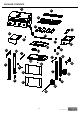
PACKAGE CONTENTS D A B C C1 E D1 F Y Z B1 G H X A1 I W U V M G N J k T O L R S P R Q 5 lowes.
PACKAGE CONTENTS PART DESCRIPTION QUANTITY PART DESCRIPTION QUANTITY A Warming rack 1 P Cart front panel bottom 1 B Cooking grate 2 Q Axle 1 C Flame tamer 4 R Wheel 2 D Grill head 1 S Corner brace right 1 E Left side shelf 1 T Cart leg front right 1 F Hood stop left 1 U Cart leg back right 1 1 G Cart side brace 2 V Grease tray bracket right H Cart leg back left 1 W Control knob 1 I Grease tray bracket left 1 X Side burner knob bezel 1 J Cart leg f
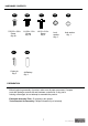
HARDWARE CONTENTS AA 5/32-32 x 3/8 in. Screw Qty.49 FF Cotter pin Qty. 3 BB BB 1/4-20 x 1/2 in. Screw Qty. 24 CC DD EE B 1/4-20 x 3/4 in. Screw Qty. 4 Lock washer Qty. 6 Axle washer Qty. 1 GG AA Battery Qty. 1 PREPARATION Before beginning assembly of product, make sure all parts are present. Compare parts with package contents list and hardware contents list. If any part is missing or damaged, do not attempt to assemble the product.
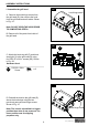
ASSEMBLY INSTRUCTIONS 1. Assemble the grill hood 1A hood hinge screw A. Remove the hood hinge screws from the grill head (D), then remove the hood from the grill head and set it aside. Shown in Fig. 1A . Note: DO NOT OPEN THE HOOD PRIOR TO COMPLETING STEP A. B. Remove all of the parts from inside of the grill head. 1B F Y C. Attach the hood stop left (F) and hood stop right (Y) to the grill head (D) using four 5/32-32 x 3/8 in. screws (AA). Shown in Fig. 1B. Hardware Used AA 5/32-32 x 3/8 in.
1D E. Open the hood and then secure the hood hinge screws in place using two cotter pins (FF). Shown in Fig. 1D. Note˖ ˖Put the assembled grill & hood to the side and then proceed to the next steps. Hardware Used FF Cotter pin FF x2 2. Assemble the left cart side Attach the cart leg back left (H) and cart leg front left (J) to the cart side brace˄G˅ using four 1/4-20 x 1/2 in. screws˄BB˅ and four 5/32-32 x 3/8 in. screws˄AA). Shown in Fig. 2. 2 BB AA Hardware Used AA 5/32-32 x 3/8 in.
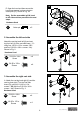
4. Assemble the wheels Slide the axle (Q) through one wheel (R) and then through the right cart side and then the second wheel (R). Secure in place using the axle washer˄EE˅and a cotter pin˄FF). Shown in Fig. 4. 4 EE FF Hardware Used EE Axle washer x1 FF Cotter pin x1 Q R FF 5 5. Assemble the front cart panel bottom A. Attach the cart front panel bottom˄P˅ to the left cart side assembly and then to the right cart side assembly using four 5/32-32 x 3/8 in. screws (AA). Shown in Fig. 5.
7 7. Assemble the cart back brace AA Attach the cart back brace˄D1˅on to the left cart side assembly and then to the right cart side assembly using four 5/32-32 x 3/8 in. screws (AA). Shown in Fig. 7. H D1 Hardware Used AA 5/32-32 x 3/8 in. Screw U x4 8 8. Assemble the LP tank bolt LP tank bolt A. Remove the LP tank bolt from the Cart base˄M). Shown in Fig. 8. M LP tank bolt B. Reinstall the LP tank bolt as shown in Fig. 8. 9.
10. Assemble the cart front panel bracket Attach the cart front panel bracket˄N˅to the cart base ˄M˅ and the cart front panel bottom ˄P˅by using two 5/32-32 x 3/8 in. screws˄AA). Show in Fig. 10. 10 AA N M P Hardware Used AA 5/32-32 x 3/8 in. Screw x2 11 AA 11. Assemble the corner brace E. Turn the cart right side up and then attached the corner brace left (L˅and the corner brace right (S) to the cart base (M) and back cart legs using three 5/32-32 x 3/8 in. screws (AA). Shown in Fig 11.
. Attach the LP tank barrier bar 13 K A.Slide the solid end of the LP tank barrier bar (K) into the hole in the cart front panel. Shown in Fig 13. B.Attach the other end to the cart base (M) using one 5/32-32 x 3/8 in. screw˄AA). Shown in Fig. 13. O ˖Make sure all cart screws are Note˖ securely tightened before proceeding to the next steps. AA Hardware Used AA 5/32-32 x 3/8 in. Screw M x1 14A 14. Assemble the grill and cart A.
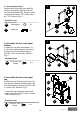
15. Install the left side shelf 15A A. Hang the left side shelf (E) on the side shelf brackets on the outside of the grill head (D) as shown in Fig. 15A. E B. Attach the shelf using three 1/4-20 x 1/2 in. screws˄BB˅and three lock washers (DD˅through the holes on inside of the grill as shown in Fig. 15B. Note: DO NOT TIGHTEN THESE SCREWS YET. 15B D Hardware Used BB DD DD 1/4-20 x 1/2 in. Screw x3 Lock washer x3 BB E C. Use one 1/4-20 x 1/2 in.
16A 16. Install the side burner shelf A. Hang the side burner shelf (Z) on the side shelf brackets on the outside of the grill head (D) as shown in Fig. 16A. Z B. Attach the side burner shelf (Z) using three 1/4-20 x 1/2 in. screws˄BB˅and three lock washers (DD˅through the holes on inside of the grill as shown in Fig. 16B. Note: DO NOT TIGHTEN THESE SCREWS YET. 16B Hardware Used BB D BB DD 1/4-20 x 1/2 in. Screw x3 Lock washer x3 DD Z C. Use one 1/4-20 x 1/2 in.
17. Attach the side burner valve 17 A. Loosen but do not remove the two preinstalled screws from the side burner valve. B. Insert the side burner valve screws through the keyhole slots in the front of the side burner shelf and then slide the valve upward so the screws rest in the small section of the keyhole slots. X C. Place the side burner knob bezel (X) keyhole slots over the side burner valve screws.
20. Install the grease tray and the grease cup 20 Slide the grease tray˄B1˅into the grease tray brackets underneath the grill. The slide the grease cup˄A1˅into the grease tray as shown in Fig. 20. I A1 B1 V 21 21. Install the side burner knob and the battery GG A. Insert the control knob (W) into the side burner valve stem as shown in Fig. 21 B. Unscrew the electronic igniter push button and then insert the AA battery (GG) with the positive (+) end pointing outward.
INSTALLATION INSTRUCTIONS For Portable LP-Gas Connection From front of the cart, place foot ring of 20 lb. tank into the hole in bottom panel. Make sure the tank valve is in OFF position. Use the tank bolt to secure the tank in a fixed position. Use only a 20 lb. gas tank (See LP Gas Safety Requirements on page 24 for additional information). It is unsafe to operate the grill if the gas tank is not vertical, as seen in Fig. 24. Fig. 23 Fig. 24 WARNING: The Type I connective coupling (see Fig.
INSTALLATION INSTRUCTIONS 2. When connecting the regulator/burner valve assembly to the tank valve, turn the large plastic nut clockwise until it stops. 3. Gas will not flow unless the plastic nut is completely connected. 4. HAND TIGHTEN ONLY. b. Hand Disassembly: 1. Make certain the tank valve and all the appliance valves are in the “OFF” position. 2. 3. Turn the large plastic nut counterclockwise until it is disassembled. HAND LOOSEN ONLY. c.
INSTALLATION INSTRUCTIONS LP Gas If your grill is for LP gas, the regulator supplied is set for 11 in. water column (WC) and is for use with LP gas only. The factory-supplied regulator and hose must be used with a 20 lb. LP gas tank.
OPERATING INSTRUCTIONS Grill Lighting Instructions To Light the Main Burners and the Side Burner 1. Make sure the control knobs are in the “OFF” position. 2. Open the grill hood. 3. Check the ignition pin position and distance between the pin and the burner. 4. Make sure the drip tray is installed. 5. Open the LPG tank or natural gas valve. 6. Light each burner separately. Turning on two burner valves together could trip the flow limiting device in the tank connection ( LP grills only). 7.
OPERATING INSTRUCTIONS Match Lighting Instructions IMPORTANT: The hood must be open when match lighting any burner. 1. Turn on gas supply. a. If portable, at the LP cylinder valve. b. If permanent gas supply, at the manual gas shutoff valve. 2. Locate the flame observation holes on each side. 3. Access the match clip with chain. 4. Attach either the match or paper to the clip (Fig.
OPERATING INSTRUCTIONS Preheating Grill It is extremely important that your grill be up to temperature before you begin using it. After lighting, close the hood and preheat the grill on “HIGH” for 15 minutes. This preheating will ensure that the cooking grid and grate are hot enough for proper grilling. CAUTION: Do not cover the grids during the preheating period. WARNING: Never leave a grill unattended to guard against possible grease fires getting out of control.
CARE AND MAINTENANCE Burner Flame Check 1 in. (2.5cm) Visually check the burner flames prior to each use. The flames should appear blue. If they do not, refer to the section on cleaning burner tubes and ports. Before cooking on your grill the first time, wash cooking grids and cooking rack with warm, soapy water. Rinse and dry thoroughly. Season with cooking oil regularly. After cooking is completed, turn grill to HIGH setting for 3 to 5 minutes to burn off excess grease or food residue.
CARE AND MAINTENANCE ! WARNING Do not attempt to turn off the LP tank valve without first covering your hand with a protective mitt or allowing the grill to cool down. Failure to follow this warning could result in a severe burn. ! LP Gas Safety Requirements For LP gas grills, the LP gas supply tank to be used must be: Constructed and marked in accordance with the Specifications for LP Gas Tanks of the U.S.
CARE AND MAINTENANCE Handling the Liquid Propane Tank Safely Remember to handle your portable liquid propane tank carefully when you take it to your dealer for a refill. Avoid dropping it or bumping it against sharp objects. Liquid propane tanks are sturdily constructed, but a series of hard jolts could damage the container. When transporting the tank to your local propane gas dealer, make sure the valve is closed tightly and the protective cover is in place.
CARE AND MAINTENANCE WARNING: When not connected to your grill, the LP gas tank must be stored in an upright position in a cool, shady, well-ventilated, outdoor location away from your grill or any other heat source. Failure to follow this warning could lead to tank valve damage, fire hazard and personal injury. Refilling a Propane Tank It is extremely important that your LP tank be filled properly when you take it to be refilled.
CARE AND MAINTENANCE Specks of grease can gather on the surface of the stainless steel and get baked-on. These can usually be removed with warm soapy water or a stainless steel cleaner. As a last resort, a mild abrasive pad could be used with a stainless cleaner. Use light pressure on the pad and always scrub in the direction of the grain. There are many outstanding products that will help clean and protect on all non-cooking surfaces. Do not use steel wool to clean the grill.
CARE AND MAINTENANCE Care and Maintenance Time Table Chart Grill Item Frequency Based on Normal Use Cleaning Method Painted surface Twice yearly Car wax Stainless surface Twice yearly Stainless cleaner All grates After each use Burn off and wipe Stainless grates 15 days Wire brush/Dishwasher safe Porcelain grates 15 days Scrub pad soapy water/ Dishwasher safe Burner heat tents 30 days Wire brush Burners 90 days Wire brush Burner box interior 120 days Interior grill cleaning product
TROUBLESHOOTING PROBLEM POSSIBLE CAUSE CORRECTIVE ACTION Grill or side cooker will not light. 1. The ignition wire came off the electrical igniter/valve. 1. Reconnect the ignition wire to the electrical igniter/valve. 2. Loosen the ignition pin and adjust the 2. The distance between the ignition pin and the burner is greater than 5/32 in.-3/16 in. (side burner). 3. The ignition wire is broken. 4. The battery has died. 5. The battery is in the wrong polarity. 6.
TROUBLESHOOTING PROBLEM POSSIBLE CAUSE CORRECTIVE ACTION Low heat with the knob in “HIGH” position. 1. Ports are blocked. 1. Clear ports of any obstructions. Low heat, LP gas. The propane regulator assembly incorporates an excess flow device designed to supply the grill with 2. Refill the LP tank. 2. LP tank has run out. sufficient gas flow. Rapid changes in pressure can trigger the excess flow device, providing a low flame and low temperature. Please follow these instructions: 1.
WARRANTY Proof of purchase is required to access this warranty program, which is in effect from the date of purchase. Customers will be subject to parts, shipping, and handling fees if unable to provide proof of the purchase or after the warranty has expired. If you have any questions or problems, you can call our customer service department at 1-800-963-0211, 8 a.m. - 6 p.m., EST, Monday - Thursday, 8 a.m. - 5 p.m., EST, Friday. Limited Warranty 5-Year Warranty on stainless steel burners.
EXPLODED VIEW 33 lowes.
REPLACEMENT PARTS LIST PART DESCRIPTION QTY. PART DESCRIPTION QTY.
REPLACEMENT PARTS LIST PART DESCRIPTION QTY. PART DESCRIPTION QTY. 47 COOKING GRATE 2 61 MAIN BURNER ELECTRODE A 1 48 GREASE TRAY BRACKET RIGHT 1 62 MAIN BURNER ELECTRODE B 1 49 SIDE BURNER KNOB BEZEL 1 63 MAIN BURNER ELECTRODE C 1 50 SIDE BURNER CONTROL PANEL 1 64 MAIN BURNER ELECTRODE D 1 51 SIDE SHELF BRACKET RIGHT 1 65 FLAME TAMER 4 52 RIGHT SIDE SHELF 1 66 BUMPER 2 53 GREASE TRAY 1 67 AA 5/32-32 X 3/8 IN.
ARTÍCULO #0503231 PARILLA DE 4 QUEMADORES Master Forge y el diseño de la M son marcas registradas de LF, LLC. Todos los derechos reservados CON QUEMADOR LATERAL MODELO #RT2417S English p. 1 ADVERTENCIA La instalación, ajuste,alteración, servicio o mantenimiento inadecuados pueden causar lesiones o daños materiales.Lea este manual de instrucciones detenidamente antes de instalar o dar servicio a este equipo. ADVERTENCIA 1.
TABLA DE CONTENIDO Información de seguridad ……………………………………………………………………….38 Contenido del paquete ……………………………..…………………….…………………........41 Aditamentos ………………………………….……………………….………....…….…..….……42 Preparación ………………….…….………………………….……………….…..……...….…….42 Instrucciones para el ensamblaje ……………………..…………….…..………….……..……43 Instrucciones para la instalación ………………………………..……………………………..53 Instrucciones de uso ……………………………………….…………………………………….56 Cuidado y mantenimiento ……………………………………………………………………….
INFORMACIÓN DE SEGURIDAD Por favor, lea y entienda este manual en su totalidad antes de intentar ensamblar, instalar o usar este Producto. Si tiene alguna pregunta sobre este producto, por favor, llame al departamento de servicio al cliente al 1-800-963-0211, entre 8:00 a.m. y 6:00 p.m., hora estándar del este, de lunes a jueves, y entre 8:00 a.m. y 5:00 p.m., hora estándar del este, los viernes. 1.
INFORMACIÓN DE SEGURIDAD 17. No guarde un cilindro de repuesto de gas propano líquido debajo o cerca de esta parrilla.. 18. Nunca llene el cilindro más del 80% de su capacidad. 19. Si las instrucciones del No. 17 y del No. 18 no se siguen exactamente, puede ocurrir un fuego y causar graves lesiones o la muerte. 20.
CONTENIDO DEL PAQUETE D A B C C1 E D1 F Y Z B1 G H X A1 I W U V M G N J k T O L R S P R Q 40 lowes.
PACKAGE CONTENTS PIEZA DESCRIPCIÓN CANTIDAD PIEZA DESCRIPCIÓN CANTIDAD A Parrilla para calentar 1 P Parte inferior del panel Delantero del carro 1 B Parrilla de cocción 2 Q Eje 1 C Difusor de llama 4 R Rueda 2 S Refuerzo esquinero derecho 1 T Pata delantera derecha del carro 1 U Pata trasera derecha del carro 1 1 D Tapa de la parrilla 1 E Repisa izquierda 1 F Tope izquierdo para la tapa G Refuerzo izquierdo del carro 2 V Soporte derecho de la bandeja degoteo H
HARDWARE CONTENTS AA BB BB CC Tornillos de Tornillos de Tornillos de 5/32-32 x 3/8 plug. 1/4-20 x 1/2 plug. 1/4-20 x 3/4 plug. Cantidad: 49 Cantidad: 24 Cantidad: 24 FF Pasador de retención Cantidad: 3 DD Arandela de presión. Cantidad: 6 EE Arandela del eje. Cantidad: 1 GG Batería AA. Cantidad: 1 PREPARACIÓN Antes de empezar a ensamblar la parrilla, asegúrese de que todas las partes estén completas. Compare las piezas con la lista de contenido del paquete y de los aditamentos.
INSTRUCCIONES PARA EL ENSAMBLAJE 1A 1. Ensamble la tapa de la parrilla. tornillo de bisagra de la tapa A. Quite los tornillos de la bisagra de la tapa para separarla de la parte superior de la tapa de la parrilla (D), luego quite la tapa separándola de la parte superior y póngala a un lado. Como se muestra en la Fig. 1A. Nota: NO ABRA LA TAPA ANTES DE COMPLETAR EL PASO A. B. Quite todas las piezas del interior de la tapa de la parrilla. C.
1D E. Abra la tapa y luego asegure los tornillos de la bisagra de la tapa en su lugar usando dos pasadores de retención (FF). Como se muestra en la Fig. 1D. Nota: Coloque la parrilla y la tapa ensamblada a un lado y luego continúe con los siguientespasos. FF Aditamentos usados FF Pasador de retención x2 2. Ensamble el lado izquierdo del carro Fije la pata izquierda trasera del carro (H) y la pata izquierda delantera (J) al refuerzo lateral del carro (G) usando cuatro tornillos 1/4-20 x 1/2 pulg.
4. Ensamble las ruedas. Deslice el eje (Q) a través de una rueda (R) y luego a través del lado derecho del carro y luego la segunda rueda (R). Asegúrelo usando la arandela del eje (EE) y el pasador de retención (FF). Como se muestra en la Fig. 4. 4 Aditamentos usados EE EE FF Q Arendela del eje x1 FF Pasador de retención R x1 FF 5 5. Ensamble el panel inferior frontal del carro A.
7 7. Ensamble el refuerzo trasero del carro Fije el refuerzo tracero del carro (D1) al lateral izquierdo del carro y luego al lateral derecho del carro usando cuatro tornillos 5/32-32 x 3/8 pulg. (AA). Como se muestra en la Fig. 7. AA H D1 U Aditamentos usados AA Tornillos 5/32-32 x 3/8 pulg. x4 perno del tanque de propano líquido 8 8. Ensamble el perno del tanque de propano líquido. A. Retire el perno del tanque de propano líquido de la base del carro (M). Como se muestra en la Fig. 8.
10. Ensamble el soporte del panel frontal del carro Fije el soporte del panel frontal del carro (N) a la base del carro (M) y a la parte inferior del panel frontal (P) usando dos tornillos de 5/32-32 x 3/8 pulg. (AA). Como se muestra en la Fig. 10. 10 AA N M P Aditamentos usados AA Tornillos 5/32-32 x 3/8 pulg. x2 11 11. Ensamble el refuerzo esquinero E.
13. Fije la barra de contención del tanque de propano líquido A. Deslice el extremo sólido de la barra de contención del tanque de propano líquido (K) en el hoyo del panel frontal del carro. Como se muestra en la Fig. 13. B. Fije el otro extremo a la base del carro (M) usando un tornillo de 5/32-32 x 3/8 pulg. (AA). Como se muestra en la Fig. 13. 13 K O Nota: Asegúrese de que todos los tornillos estén bien apretados antes de continuar conlos próximos pasos.
15. Instale la repisa lateral izquierda A. Cuelgue la repisa lateral izquierda (E) sobre los soportes para la repisa lateral en el lado de la parte superior de la parrilla (D) como se muestra e la Fig. 15A. 15A E B. Fije la repisa usando tres tornillos de 1/4-20 x 1/2 pulg. (BB) y tres arandelas de presión (DD) poniéndolas en los hoyos en el interior de la parrilla como se muestra en la Fig. 15B. Nota: NO APRIETE ESTOS TORNILLOS TODAVÍA. 15B D Aditamentos usados DD BB Tornillos de1/4-20 x 1/2 plug.
16A 16. Instale la repisa lateral del quemador A. Coloque la repisa lateral del quemador (Z) en los soportes laterales de la repisa en la parte exterior de la parte superior de la parrilla (D) como se muestra en la Fig. 16A. Z B. Coloque la repisa lateral del quemador (Z) usando tres tornillos de 1/4-20 x 1/2 pulg. y tres arandelas de presión (DD) en los hoyos interiores de la parrila como se muestra en la Fig. 16B. Nota: NO APRIETE ESTOS TORNILLOS TODAVÍA.
17. Coloque la válvula del quemador lateral A. Afloje pero no quite los dos tornillos. preinstalados de la válvula del quemador lateral. B. Inserte los tornillos de la válvula del quemador lateral a través de las ranuras en la parte delantera de la repisa del quemador lateral y luego deslice la válvula hacia arriba para que los tornillos descansen en la pequeña sección de las ranuras. C.
20. Instale la bandeja de goteo y la taza de goteo Deslice la bandeja de goteo (B1) en los soportes de la bandeja debajo de la parrilla. Luego deslice la taza de goteo (A1) en la bandeja de goteo como se muestra en la Fig. 20. 20 I A1 B1 V 21. Instale la perilla del quemador lateral y la batería 21 GG A. Coloque la parilla del control (W) en el vástago de la válvula del quemador lateral como se muestra en la Fig. 21. B.
INSTRUCCIONES PARA LA INSTALACIÓN Para la conexión de gas propano líquido portátil En el frente del carro, coloque el aro del tanque de 20 lb. en el panel inferior. Asegúrese de que la válvula del tanque esté en la posición OFF. Use el perno del tanque para asegurar el tanque en una posición fija. Use solanmente un tanque de 20lbs. (Consulte los Requisitos de seguridad para gas propano líquido en la página 59 para más información).
INSTRUCCIONES PARA LA INSTALACIÓN 2. Cuando conecte el conjunto de la válvula del quemador/regulador, gire la tuerca plástica grande hacia la derecha hasta que se detenga. 3. El gas no fluirá a menos que la tuerca plástica esté completamente conectada. 4. APRIÉTELA CON LA MANO SOLAMENTE. b. Desmontaje a mano : 1. Asegúrese de que la válvula del tanque y todas las válvulas de la parrilla estén en la posición “OFF” (apagado). 2. Gire la tuerca plástica grande hacia la izquierda hasta que se suelte. 3.
INSTRUCCIONES PARA LA INSTALCIÓN Gas propano líquido Si su parrilla es para gas propano líquido, el regulador suministrado está hecho para columna de agua (WC) de 27,94 cm y es para usar con gas propano líquido solamente. El regulador y la manguera de fábrica deben estar con un tanque de gas propano líquido de 20 lbs.
INSTRUCCIONES DE USO Instrucciones para encender la parrilla Para encender el quemador principal y los laterales 1. Asegúrese de que las perillas de control estén en la posición “OFF” (apagado). 2. Abra la tapa de la parrilla. 3. Verifique la posición del pasador de encendido y la distancia entre el pasador y el quemador. 4. Asegúrese de que la bandeja de goteo está instalada. 5. Abra la válvula del tanque de gas propano líquido o de gas natural. 6. Encienda cada quemador por separado.
INSTRUCCIONES DE USO Instrucciones para encender con cerillas IMPORTANTE: Para encender con cerillas cualquier quemador, la tapa debe estar abierta. 1. Abra el suministro de gas. a. Si es portátil, la válvula del tanque de gas de propano líquido. b. Si es suministro de gas permanente, la válvula de cierre manual. 2. Localice los agujeros de observación de llama en cada lado. 3. Acceda a la presilla con cadena para la cerrilla. 4. Fije la cerilla o papel con la presilla (Fig.
INSTRUCCIONES DE USO Precalentamiento de la parrilla Es sumamente importante que su parrilla esté a buena temperatura antes de empezar a usarla. Después de encenderla, cierre la tapa y precaliente la parrilla en “HIGH” durante 15 minutos. Este Precalentamiento asegurará de que la parrilla y parrilla de cocción estén lo suficientemente calientes como para asar adecuadamente. PRECAUCIÓN: No cubra las parrillas durante el período de precalentamiento.
CUIDADO Y MANTENIMIENTO Verifique visualmente las llamas del quemador antes de cada uso. Las llamas deben ser azules. Si no es así, consulte la sección de limpieza de tuberías y puertos de los quemadores. Antes de cocinar en su parrilla por primera vez, lave las parrillas y rejillas de cocción con agua tibia y 1 pulg. (2,5 cm) jabón. Enjuáguelas y séquelas bien. Engráselas con. aceite de cocina regularmente.
CUIDADO Y MANTENIMIENTO ! ADVERTENCIA No intente cerrar la válvula del tanque de gas sin cubrir primero su mano con un guante de protección o dejar que la parrilla se enfríe. El incumplimiento de esta advertencia puede resultar en una quemadura grave.
CUIDADO Y MANTENIMIENTO Manipulación segura del tanque de propano líquido Recuerde manipular con cuidado el tanque de propano líquido portátil cuando lo lleve al distribuidor para rellenarlo. Evite caídas o golpes contra objetos afilados. Los tanques de propano líquido están sólidamente construidos pero unas sacudidas bruscas pueden dañar el cilindro.
CARE AND MAINTENANCE ADVERTENCIA: Cuando no esté conectado a la parrilla, el tanque de gas de propano líquido debe ser almacenado en posición vertical en un lugar al aire libre, fresco, a la sombra y bien ventilado, lejos de su parrilla o cualquier otra fuente de calor. El incumplimiento de esta advertencia puede provocar daños en la válvula del tanque, riesgo de incendio y lesiones personales.
CUIDADO Y MANTENIMIENTO Las manchas de grasa que caen y se queman en la superficie del acero inoxidable, por lo general, se pueden quitar con agua tibia y jabón o un limpiador de acero inoxidable. Ponga ligera presión sobre la almohadilla y siempre frote en dirección de la veta. Hay muchos productos excelentes que le ayudarán a limpiar y proteger todas las superficies que no son de cocción. No use estropajos de metal para limpiar la parrilla No use limpiadores abrasivos en la superficie pulida.
CUIDADO Y MANTENIMIENTO Calendario de cuidado y mantenimiento Artículo de parrilla Frecuencia según el uso Método de limpieza normal Superficie pintada Dos veces al año Cera para automóviles Superficie de acero inoxidable Dos veces al año Limpiador para acero inoxidable Todas las rejillas Después de cada uso Queme y limpie Rejillas de acero inoxidable 15 días Apto para cepillo de alambre/lavaplatos Rejillas de porcelana 15 días Almohadilla para frotar agua jabonosa/ Apto para lavaplatos Cám
DETECCIÓN DE PROBLEMAS PROBLEMA POSIBLECAUSA ACCIÓNCORRECTIVA La parrilla o el quemador lateral no enciende. 1.El cable de encendido se desprendió del encendedor eléctrico/de la válvula. 2.La distancia entre el pasador de encendido y el quemador es más de3,964,72mm (quemador lateral). 3.El cable de encendido está roto. 4.La batería murió. 5.La batería está con la polaridad incorrecta. 6.La punta del electrodo no produce chispas en el puerto del quemador. 7.No entra el gas. 8.
DETECCIÓN DE PROBLEMAS PROBLEMA ACCIÓNCORRECTIVA POSIBLECAUSA Temperatura baja con la perilla en la posición“HIGH”. 1.Los puertos estánb bloqueados. 2.El tanque de propano líquido se ha terminado. 1.Limpie los puertos de cualquier obstrucción. 2.Rellene al tanque de propano líquido. Baja temperatura, gas propano líquido. El del regulador de propano tiene un dispositivo de exceso de flujo diseñado para suministrar a la parrilla suficiente flujo de gas.
GARANTÍA Se requiere una prueba de la compra para acceder a este programa de garantía que entra en vigor a partir de la fecha de compra. Los clientes serán responsables de pagar los costos de las piezas, el envío y el manejo si no se presenta una prueba de compra, o después del vencimiento de la garantía. Si tiene alguna pregunta o problema, puede llamar a nuestro departamento de servicio al cliente al 1-800-963-0211, de 8 a.m. a 6 p.m., hora del este, de lunes a jueves, y de 8 a.m. a 5 p.m.
VISTAAMPLIADA 68 lowes.
REPLACEMENT PARTS LIST PIEZA DESCRIPCIÓN CANTIDAD PIEZA DESCRIPCIÓN CANTIDAD 1 TAPA DE LAPARRILLA 1 24 PERILLA 5 2 TORNILLO DE LA BISAGRA DE LA TAPA 2 25 REPISA LATERAL IZQUIERDA 1 3 MOLDURA DEL INDICADOR DE TEMPERATURA 1 26 FRENTE DE LA REPISA LATERAL IZQUIERDA 1 4 ESPACIADOR AISLANTE TÉRMICO DEL INDICADOR DE TEMPERATURA 1 27 PATA FRONTAL IZQUIERDADEL CARRO 1 5 INDICADOR DE TEMPERATURA 1 28 REFUERZO LATERAL DEL CARRO 2 6 PARRILLA PARA CALENTAR 1 29 PATA TRASERA IZQUI
REPLACEMENT PARTS LIST PIEZA DESCRIPCIÓN CANTIDAD PIEZA DESCRIPCIÓN CANTIDAD 47 PARRILLA DE COCCIÓN 2 61 ELECTRODO A DEL QUEMADOR PRINCIPAL 1 48 SOPORTE DERECHO DELA BANDEJA DE GOTEO 1 62 ELECTRODO B DEL QUEMADOR PRINCIPAL 49 MOLDADURA DE LA PERILLA DEL QUEMADOR LATERAL 1 63 ELECTRODO C DEL QUEMADOR PRINCIPAL 50 PANEL DE CONTROL DEL QUEMADOR LATERAL 1 64 ELECTRODO D DEL QUEMADOR PRINCIPAL 51 SOPORTE DE LAREPISA LATERAL DERECHA 1 65 DIFUSOR DE LLAMA 52 REPISA LATERAL DERECHA