
Installation Manual


8
ChargeMaster Plus 12/75-3, 12/100-3, 24/40-3, 24/60-3 – User and Installation Manual
3 INSTALLATION
During installation and commissioning, the safety
instructions are applicable at all times.
3.1 Unpacking
In addition to the ChargeMaster Plus the delivery
includes:
• Mounting bracket to mount the ChargeMaster
Plus to a wall;
• Battery temperature sensor;
• Drop cable CZone/MB (1m);
• MasterBus Terminator;
• User manual.
After unpacking, check the contents for possible
damage. Do not use the product if it is damaged.
If in doubt, contact your supplier
Check from the identification label (see section
1.2) whether the battery voltage is the same as
the nominal output voltage of the ChargeMaster
Plus (e.g. 24V battery set for a 24V battery
charger).
3.2 Location
• The ChargeMaster Plus is designed for indoor
use only.
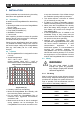
• Ambient temperature:
-25°C ... 80°C / -13°F … 176°F;
(power derating above 40°C / 104°F to
decrease the internal heat sink temperature).
• Humidity: 0-95% non-condensing
• Mount the ChargeMaster Plus vertically, with
the connecting cables downwards.
• Do not expose the ChargeMaster Plus to
excessive dust, aggressive environments,
ammonia or salt.
• Make sure that the hot air that is developed
during operation can be discharged. The
ChargeMaster Plus must be mounted in such
a way that obstruction of the airflow through
the ventilation openings will be prevented.
• This device requires a minimum of 100mm
(4") of clearance on every side.
• If added to a CZone or MasterBus network,
take the network powering into consideration.
• Never place the ChargeMaster Plus directly
above the battery being charged, as gases
from battery will corrode and damage the
ChargeMaster Plus.
• If the ChargeMaster Plus is installed in the
immediate vicinity of living areas, take into
account that the fan of the ChargeMaster Plus
can produce noise when operating.
• Although the ChargeMaster Plus fully
complies with all applicable EMC limits, it may
still cause harmful interference to radio
communication equipment. If such
interference appears, it is recommended to
increase the separation between the
ChargeMaster Plus and the equipment, to
relocate the receiving antenna or to connect
the equipment to a circuit different from that
to which the ChargeMaster Plus is connected.
3.3 Wiring
WARNING!
The wire sizes stated in this
manual are given as guideline
only. Always comply with all local
rules and regulations.
3.3.1 DC wiring
Keep in mind that high current will pass through
the DC wiring. Keep the cable length as short as
possible, this will keep the system efficiency as
high as possible. The recommended minimum
cross section of the battery cables is:
ChargeMaster
Plus model
DC Cable cross section:
<3m / 10ft
3-5m / 10-16ft
12/75-3
25mm² /
AWG2
35mm² /
AWG1
12/100-3
35mm² /
AWG1
50mm² /
AWG0
24/40-3
16mm² /
AWG4
25mm² /
AWG2
24/60-3
25mm² /
AWG2
35mm² /
AWG2
0
20
40
60
80
100
120
-50
-40
-30
-20
-10
0
10
20
30
40
50
60
70
80
90
100
Output Power (%)
Temperature (°C)
Output Power vs Temperature