
Datasheet


3
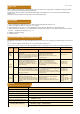
PERFORMANCE
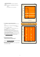
FUSING CHARACTERISTICS
I
2
T - T CHARACTERISTICS
No Item
1 Temperature rise
2 Current-carrying capacity
3 Clearing characteristics
4 Voltage drop
5 Fusing characteristics
6 Insulation resistance
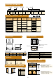
7
Electrode strength
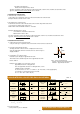
(Bending)
Board supporting width
Bending speed
Duration
Bending
: 90mm
: Approx. 0.5mm/s
: 5 s
: 3mm
Applied force
Duration
Tool
: 20N
: 10s
: R0.5
Supporting dimension
Applied force
Duration
Tool
: 3.65mm
: 20N
: 10s
: R0.5
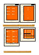
Solder
Temperature
: Sn-3Ag-0.5Cu
: 245±5℃
11
Solderability
(new uniform coating of
solder)
Solder
Temperature
Dippinng
: Sn-3Ag-0.5Cu
: 245±5℃
: 3s
Preconditioning
Temperature
: 100~150℃/60s
: 265±3℃/6~7s
Preconditioning
Peak
Holding
Cooling
: Lower than 180℃ 1~2min
: 250±5℃ 5s
: 230~250℃ 30~40s
: More than 2min
Temperature
Duration
: 350±10℃
: 3~4s
Solvent
Duration
: Isopropyl alcohol
: 90s
14 Vibration
Frequency rage
Vibration amplitude
Duration
: 10~55~10Hz/min
: 1.5mm
: 2 hours in each of XYZ directions
(total : 6 hours)
Peak value
Duration
: 490m/s
2
: 11ms
-55±3℃
Room temperature
125±2℃
Room temperature
: 30min
: 2~3min or less
: 30min
: 2~3min or less
17 Moisture resistance
Temperature
Humidity
Duration
: 85±3℃
: 85±5%RH
: 1000h
18 Load life
Temperature
Applied current
Duration
: 85±2℃
: Rated current×70%
: 1000h
19 Moisture resistance load
Temperature
Humidity
Applied current
Duration
: 85±3℃
: 85±5%RH
: Rated current×70%
: 1000h
20 Stability
Temperature
Duration
: 125±2℃
: 1000h
13
16
Thermal shock
Shock
The dipping surface of the terminals shall be covered
more than 95% with new solder.
No mechanical damage.
Resistance change after the test shall be within ± 20%.
No mechanical damage.
Resistance change after the test shall be within ± 20%.
No mechanical damage.
Resistance change after the test shall be within ± 20%.
Marking shall be legible.
No mechanical damage.
Resistance change after the test shall be within ± 20%.
12
Insulation resistance between terminals and case(ceramics)
Breaking voltage : Rated voltage
Breaking current : 300A(30~50A)、600A(60~100A)
Fusing within I min.
Apply rated current
1000MΩ or more
Arc shall not be continued.
No ignition.
Marking shall be legible
No bursting of the fuse
Voltage drop is below the value specified in CATALOG
NUMBERS AND RATING.
Direction of the press : thickness direction of product
Direction of the press : side face
No mechanical damage.
Resistance change after the test shall be within ± 20%.
No mechanical damage.
Resistance change after the test shall be within ± 20%.
Test method
Apply rated current
Apply 100% of rated current
Performance
Temperature rise shall not exceed 75℃
Apply 250% of rated current
(Ambient temperature: 10~30℃)
Shall not open within 1 hour.
8
Shear test
9
Core body strength
10
Solderability
(Solder Wetting time)
No mechanical damage.
Resistance change after the test shall be within ± 20%.
Repeat above step for 10 cycles
No mechanical damage.
Resistance change after the test shall be within ± 20%.
Resistance to
soldering heat
Dipping(1 cycle)
Solder Wetting time : within 3s
meniscograph method
No mechanical damage.
Resistance change after the test shall be within ± 20%.
15
No mechanical damage.
Resistance change after the test shall be within ± 20%.
Solvent resistance
Reflow(2 cycle)
Manual soldering
Measure after 1hour left under room temperature and humidity.
No mechanical damage.
Resistance change after the test shall be within ± 20%.
Dipping rinse
Marking shall be legible.
No mechanical damage.
No significant irregularity in the appearance.
6 aspects × 3 times (total: 18 times)