
Datasheet


DS1023
5 of 16
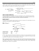
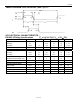
MS = 1 Figure 4
Output Function Name Pin Number
Pulse Width Modulated Output PWM 9
Delayed and Inverted Output
OUT
15
PWM is an output triggered by the rising edge of the input waveform. After a time interval approximately
equal to the Step Zero delay of the device the PWM output will go high. The output will return to a low
level after a time interval determined by the programmed values (Table 1). Hence output pulse widths can
be obtained from (nearly) zero to the full delay range of the device. In practice the minimum output pulse
width is limited by the response time of the device to approximately 5ns. Programmed values less than
this will result in degradation of the output high level voltage until ultimately no discernible output pulse
is produced. The frequency/repetition rate of the output is determined by the input frequency. The input
pulse width can be shorter than the output pulse width, and is limited only by the minimum input pulse
width specification. The PWM function is not “re-triggerable”, subsequent input trigger pulses should
not be present until the output has returned to a low level.
OUT is an inverted copy of the input waveform that is delayed by an amount set by the programmed
values (Table 1). A programmed value of zero will still result in a non-zero delay as indicated in the Step
Zero delay specification. The OUT pin may also be externally connected to the input pin to produce a
free-running oscillator. The frequency of oscillation is determined by the programmed delay value of the
device (see Table 2).