
Datasheet

DS1090
Low-Frequency, Spread-Spectrum
EconOscillator
Maxim cannot assume responsibility for use of any circuitry other than circuitry entirely embodied in a Maxim product. No circuit patent licenses are
implied. Maxim reserves the right to change the circuitry and specifications without notice at any time.
8
_____________________Maxim Integrated Products, 120 San Gabriel Drive, Sunnyvale, CA 94086 408-737-7600
© 2007 Maxim Integrated Products is a registered trademark of Maxim Integrated Products.
is a registered trademark of Dallas Semiconductor Corporation.
Dither Percentage Settings
Dither amplitude (measured in percent ± from the mas-
ter oscillator center frequency) is set using input pins
J0 and J1. This circuit uses a sense current from the
master oscillator bias circuit to adjust the amplitude of
the triangle-wave signal to a voltage level that modu-
lates the master oscillator to a percentage of its resis-
tor-set center frequency. This percentage is set in the
end application to be 0%, 2%, 4%, or 8% (see Table 2).
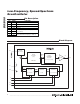
Application Information
Pin Connection
The DS1090 is intended to provide a fixed-frequency,
dithered clock to be used as a clock driver for DC-DC
converters and other applications requiring a low-
frequency EMI-reduced clock oscillator. All control pins
must be biased per Tables 1 and 2 for proper operation
for the individual application’s requirements. R
SET
must
be tied to ground (GND) by a customer-supplied resistor.
R
SET
Resistor Selection
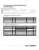
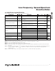
The value of the resistor used to select the desired fre-
quency is calculated using the formula in the
Master
Oscillator
section (see also Figure 1). It is recommended
to use, at minimum, a 1%-tolerance, 1/16th-watt compo-
nent with a temperature coefficient that satisfies the over-
all stability requirements desired of the end-equipment.
Place the external R
SET
resistor as close as possible to
minimize lead inductance.
Power-Supply Decoupling
To achieve best results, it is highly recommended that a
decoupling capacitor is used on the IC power-supply
pins. Typical values of decoupling capacitors are 0.01µF
and 0.1µF. Use a high-quality, ceramic, surface-mount
capacitor, and mount it as close as possible to the V
CC
and GND pins of the IC to minimize lead inductance.
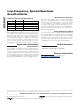
J1 J0 DITHER PERCENT (%)
00 0
01 2
10 4
11 8
Table 2. Dither Percentage Setting
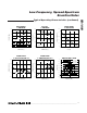
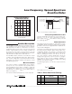
Package Information
For the latest package outline information, go to
www.maxim-ic.com/DallasPackInfo
.
Chip Information
TRANSISTOR COUNT: 1883
SUBSTRATE CONNECTED TO GROUND