
Datasheet


DS2430A
12 of 19
After one complete pass, the bus master knows the contents of the ROM in one device. The remaining
number of devices and their ROM codes may be identified by additional passes. See Application Note
187 for a comprehensive discussion of a search ROM, including an actual example.
1-Wire Signaling
The DS2430A requires strict protocols to insure data integrity. The protocol consists of four types of
signaling on one line: Reset Sequence with Reset Pulse and Presence Pulse, Write-0, Write-1 and Read-
Data. All these signals (except Presence Pulse) are initiated by the bus master.
To get from idle to active, the voltage on the 1-Wire line needs to fall from V
PUP
below the threshold V
TL
.
To get from active to idle, the voltage needs to rise from V
ILMAX
past the threshold V
TH
. The time it takes
for the voltage to make this rise is seen in Figure 9 as ε, and its duration depends on the pullup resistor
(R
PUP
) used and the capacitance of the 1-Wire network attached. The voltage V
ILMAX
is relevant for the
DS2430A when determining a logical level, not triggering any events.
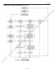
Figure 9 shows the initialization sequence required to begin any communication with the DS2430A. A
Reset Pulse followed by a Presence Pulse indicates the DS2430A is ready to receive data, given the
correct ROM and memory function command. If the bus master uses slew-rate control on the falling
edge, it must pull down the line for t
RSTL
+ t
F
to compensate for the edge.
After the bus master has released the line it goes into Receive mode. Now the 1-Wire bus is pulled to
V
PUP
through the pullup resistor. When the threshold V
TH
is crossed, the DS2340A waits for t
PDH
and then
transmits a Presence Pulse by pulling the line low for t
PDL
. To detect a Presence Pulse, the master must
test the logical state of the 1-Wire line at t
MSP
. The t
RSTH
window must be at least the sum of t
PDHMAX
,
t
PDLMAX
, and t
RECMIN
. Immediately after t
RSTH
is expired, the DS2430A is ready for data communication.
INITIALIZATION PROCEDURE “RESET AND PRESENCE PULSES” Figure 9
Read/Write Time Slots
Data communication with the DS2430A takes place in time slots, which carry a single bit each. Write
time slots transport data from bus master to slave. Read time slots transfer data from slave to master.
Figure 10 illustrates the definitions of the write and read time slots.
All communication begins with the master pulling the data line low. As the voltage on the 1-Wire line
falls below the threshold V
TL
, the DS2430A starts its internal timing generator that determines when the
data line is sampled during a write time slot and how long data is valid during a read time slot.
RESISTOR MASTER DS2430A
t
RSTL
t
PDL
t
RSTH
t
PDH
MASTER TX “RESET PULSE”
MASTER RX “PRESENCE PULSE”
V
PUP
V
IHMASTER
V
TH
V
TL
V
ILMAX
0V
ε
t
F
t
REC
t
MSP
NOT RECOMMENDED FOR NEW DESIGNS