
Datasheet


DS2430A
7 of 19
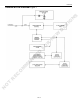
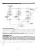
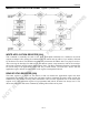
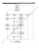
MEMORY FUNCTION FLOW CHART Figure 6 (continued)
WRITE APPLICATION REGISTER [99h]
This command is essentially the same as the Write Scratchpad command, but it addresses the 64-bit
register scratchpad. After issuing the command code, the master must provide a 1-byte address, followed
by the data to be written. The DS2430A automatically increments the address after every byte it receives.
After receiving the data byte for address 07h, the address counter wraps around to 00h for the next byte
and writing continues until the master sends a Reset Pulse. The Write Application Register command can
be used as long as the application register has not yet been locked. If issued for a device with the
application register locked, the data written to the register scratchpad will be lost.
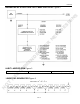
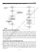
READ STATUS REGISTER [66h]
The status register is a means for the master to find out whether the application register has been
programmed and locked. After issuing the read status register command, the master must provide the
validation key 00h before receiving status information. The two least significant bits of the 8-bit status
register are 0 if the application register was programmed and locked; all other bits always read 1. The
master may finish the read status command by sending a Reset Pulse at any time.
NOT RECOMMENDED FOR NEW DESIGNS