
Datasheet


DS2430A
9 of 19
1-WIRE BUS SYSTEM
The 1-Wire bus is a system that has a single bus master and one or more slaves. In all instances, the
DS2430A is a slave device. The bus master is typically a microcontroller. The discussion of this bus
system is broken down into three topics: hardware configuration, transaction sequence, and 1-Wire
signaling (signal type and timing). The 1-Wire protocol defines bus transactions in terms of the bus state
during specified time slots that are initiated on the falling edge of sync pulses from the bus master.
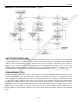
Hardware Configuration
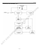
The 1-Wire bus has only a single line by definition; it is important that each device on the bus be able to
drive it at the appropriate time. To facilitate this, each device attached to the 1-Wire bus must have open
drain connection or three-state outputs. The 1-Wire port of the DS2430A is open drain with an internal
circuit equivalent to that shown in Figure 7. A multidrop bus consists of a 1-Wire bus with multiple
slaves attached. The DS2430A communicates at regular 1-Wire speed, 15.3kbits per second, and requires
a pullup resistor as shown in Figure 7. The idle state for the 1-Wire bus is high. If for any reason a
transaction needs to be suspended, the bus MUST be left in the idle state if the transaction is to resume. If
this does not occur and the bus is left low for more than 120µs, one or more of the devices on the bus may
be reset.
HARDWARE CONFIGURATION Figure 7
Note: Depending on the 1-Wire communication speed and the bus characteristics, the optimal pullup
resistor value will be in the 0.3kΩ to 2.2kΩ range. To write to a single device, a R
PUPmax
resistor and
V
PUP
of at least 4.0V is sufficient. For writing multiple DS2430As simultaneously or operation at low
V
PUP
, the resistor should be bypassed by a low-impedance pullup to V
PUP
while the device copies the
scratchpad to EEPROM.
R
PU
R
PU
I
L
NOT RECOMMENDED FOR NEW DESIGNS