
Specifications

1-4
Installation and Operation Manual
X-VA-MT3750C-eng
Part Number: 541B063AAG
April, 2014
Brooks
®
Ar-Mite
TM
MT3750C
Section 1 Introduction
1-3 Optional Equipment
Standard Needle Valves
The standard needle or cartridge valves can be supplied integrally
mounted to the inlet fitting of the instrument. The optional NRS
TM
needle
valve, also integrally mounted to the inlet fitting, provides a greater number
of turns affording precision control. For more details on the needle or
cartridge valves go to our website: BrooksInstrument.com,
select Documentation,Precision Valves and Flow Controllers,
Brooks-Line IV
TM
, CART valves or NRS valves.
Limit Switches
Inductive Alarm Switch
One or two electronic limit switches type SJ2-N can be installed in the
indicator housing to allow initiation of signaling or switching functions on a
preset flow value being reached. The SJ2-N limit switch operates as a slot
initiator that is inductively actuated by a cam mounted to the pointer. Any
flow value can be used for setting the limit value by sliding the switch along
the slot in the mounting plate for the initiators. Minimum setting distance
between two limit switches is approximately 50% of the scale range.
(Refer to Figure 1-1)
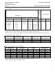
Power supply 8 Vdc (Max. 15.5 Vdc)
Current consumption active area clear: > 3 mA
Current consumption active area obscured: < 1 mA
Self inductance 29 μH
Self capacitance 20 nF
Max Temp: 158°F(70°C)
Inductive Alarm
Electrical Classification
Intrinsically Safe:
ATEX: KEMA 02ATEX1126
II 2 G Ex ia IIC T6
per EN 60079-0: 2006 EN 60079-11: 2007
EN 61241-0: 2006 EN 61241-11: 2006
II 2 D Ex iaD 21 IP65 T 75
O
C
IECEx KEM 09.0046
Ex ia IIC T6 Gb/Ex ia IIIC T 75
O
C Db IP65
per IEC 60079-0: 2007-10 IEC 60079-11: 2006
IEC 61241-11: 2005
CSA: (USA and Canada) 1379260
Class I, II, III, Div. 1, Groups A thru G, T6
per CSA -157:1992 ; UL913:2002
Class I, Zone 0, Zone 1 AEx ia IIC, T6
per ANSI/ UL 2279: 1996
Ex ia IIC
per CSA E79-0:2002; CSA E79-11:2002