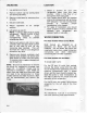
r- 56326 ] andToPMount Side-By-Side Refrigerator ServiceManual svF-0289 IN U.S.A. PRINTED o Copyright1989 -- ,-a. l..r 4-- , ,.-.-.-,=--:..
INDEX SaBIECT PAGE 1 . INTRODUCTION SECTION SECTION2 . INSTALLATION Specifications Warranty InstallationInstructions Operation 2-1 2-4 2-5 2-14 SECTION3.
MI\YTAG SECTION I INTRODUCTION GENERAL T h i s m a n u a lco ve rsMa yta gR e fri ger atormanufactur s ed beginningin 1989.Thos em odel s c o v e r e da r e 1 5 , 1 7 , 1 9 , 2 0 , 2 1 , 2 2 , 2 3 a n d 2 4 c u b i cf o o t S i d e - B y - S i daen d T o p M o u n t r e fr i g e r a t ors. SAFETYPRECAUTIONS This service informationis intendedto be used by a qualifiedservice technician,who is familiar with proper and safe procedures to be followed when repairing any electrical appliance.
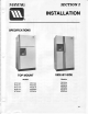
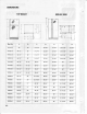
SECTION 2 M/\YTAG INSTALLATION SPECIFICATIONS TOPMOUNT Models Models R T C1 5 A R T S1 7 A R T C1 7 A R T D1 7 A R T S1 9 A SIDE.BY.
DIMENSIONS TOPMOUNT SIDE-BY.
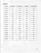
CAPACITY Mod. No. TotalVolume Fresh Food Vol. FreezerVol. Total Shelf Area RTC15A 14.7 10.51 4.14 22.6 RTS17A 16.5 11.69 4.83 23.8 RTC17A 16.5 11.69 4.83 24.2 RTD17A 16.5 11.69 4.83 24.2 RTC19A 18.6 12.89 5.70 28.6 RTS19A 18.6 12.90 5.70 26.3 RTD19A 18.5 12.81 5.70 28.4 RTD21A 21.0 '14.59 6.42 32.5 RTW22A 21.9 14.98 6.91 32.9 RTD23A 22.5 15.52 6.96 34.6 RSC2OA 20.2 13.66 6.57 24.4 RSD2OA 20.2 13.58 o.c/ 24.4 RSD22A 21.8 15.22 6.57 25.
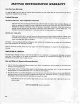
MAYTAG REFRIGERATOR WARRANTY Full One Year Warranty For one (1) year from the date of originalretail purchase,any part which fails in normalhome use will be repairedor replacedf ree of charge.
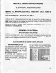
INSTALLATION INSTRUCTIONS ELECTRICAL REQUIREMENTS OBSERVEALL NATIONAL ELECTRICALCODES AND LOCAL CODES & ORDINANCES - 120VOLTS,60 Hz ONLY ELECTRICAL SERVICE A 1 2 0v o l t ,6 0 H z, 1 5 a mp e refu se delectr icalsupplyis r equir ed.An individualbr a nc h( or s e p a r a t ec i rcu i tse rvi n go n l y th i s a pplianceis r ecom m ended.)DO NOTUSEEXT EN SION C O R Du n l e ssi t me e tsa l l re q u i re ments as outlinedfor gr ounding,polar izing( 3- w i r e)and c a p a c i t y .
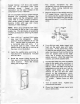
UNCRATING LOCATION en back. 1 . L a ya p p l i a n c o 1. Select a location for your new refrigerator away f rom any heat sour ces. Allow a fr ee flow o f ai r thr oughthe fr ontbasegr ille. 2. Your model should NOT be installed where the temperaturewill go below 55"F becauseif will not run frequently proper enough to maintain temperaturein the freezer. 3. For ease of installation,you shoul d leave a space of about one- hal fi nc h between your r efr iger ator and adjacentwallsor cabinets. 2 .
C o p p e rt u b i n g ( 1 1 4 "O . D . ) a n d s a d d l e v a l v e c a n b e p u rch a se d f ro m local S w e a t o r f lar e h a r d w a r e sto re s. c o n n e c t i o nca n b e u se d i n ste a dof the c o m p r e s s i ounn i o n ,i f d e s i r e d . D o n o t u s e p l a sti ctu b i n go r p l a sti cfittings b e c a u s e t he co n n e cti o n b e tw e en the water supply and the refrigeratorwater v a l v e i n l e t i s u n d e r co n sta n tp ressur e.
I' P l u gi n t h e p o w e rco rda n d p u shthe r efr iger ator to the walt,ar r angingthe coppertu bi ng s o t h a t i t d o e sn o t vi b ra tea g a i n stthe backof the r efr iger ator or againstthe wall. IMPORTANT:Becausethe refrigeratorand ice maker are warm. tt may takeup to 12 hours before the ice maker producesthe first supptyof ice cubes.
DOORS REVERSING Top MountModelsOnly Door reversal is NOT possible on those models that have a built-in ice and water lountain. However, if door removal becomes necessaryplease see the note in Step 9. Unplug Refrigerator. lf unit is in use, remove food from fresh food compartment and freezercompartment. Removingdoors. N O T E : T a p i n g d o o rs sh u t p rior to p h y s i c a l l yre mo vi n gth e m ma y pr event d a ma g e . u n n e c e s s ary 1 .
Reversinglreezer door. 10.Take freezer door and remove screw from trim cap on the top of the door. 1 1 .S l i d e b l a c kt r i m o f f o f t h e m e t a l h a n d l e bracket. H a n d l ea n d t r i m s h o u l db e c o m p l e t e l y r emovedfr omfr eezerdoor . 1 4 .Pr y plugson left side on top off w i th a flat bladescr ewdr ivertaking , car e not to damagethemor the door . 1 5 . Put plugs into exposedholes on the r ighthandside of tr eezerdoor .
1 9 . W i t h g r i l l e n o w re mo ve d ,yo u have accessto the bottomhinge. Remove s c r e wf r o mth e si d eo f th e h i n g ecover . 22. Reinstallthe tr im cap and hingec ov er on the oppositesides. 23.Nowtake refrigeratordoor and remove scr ewfr om the tr im cap locatedon the bottomof the door, 24.Slideblacktr im off m etaldoor b r ac k et. 25. Rem ovescr ew holdingm etal br ac k et at the bottom of the door, and the scr ewlocatedin the centerof the door just under neath the handle. 26.
29 .J u s t a s y o u d i d a b o vefo r th e tre e zerdoor ,moveall of the handleand tr im par tsto the o p p o s i t es id e o f th e d o o r a n d re i n stall.This is doneby r ever singthe stepsabove . N O T E : C are mu st o n ce a g a i n b e takento make sur e all spacerpads ar e r etur nedto t h e i rp r o p e rp o s i t i o n . 30 .R e i n s t a lpl l u g si n toscre wh o l e se xposedon the r ighthandside of the door . 31 .R e i n s t a ltlh e re fri g e ra todr o o r.
DOORREMOVAL ModelsOnly Side-By-Side Unplug Refrigerator. lf unit is in use, remove food from the fresh food compartmentand freezercompartment. W ithassistance fr om someoneel s e to suppor t the tr eezer door , r em ov e bottomhinge by fir st r em ovin gs c r ew fr om side of hingecover and rem ov e cover . 6. Pull wires and water line through fr ame. openingin r efr iger ator RemovingFreezerDoor 1 .
OPERATION Top MountModels SettingControls T h e s e m o d e l sh a ve tw o co n tro l s. One for r egulatingthe tem per atur ein the fr esh food compartmentand one for the freezer. The fresh food compartmentand the treezer c om p a r t m e nco t n tro l sa re l o ca te da t the top fr ontof the fr eshfoodcom par tment.Turnthe refr i g e r a t ocr o n tro lto th e n u mb e r" 5 " and the fr eezercontr olto the letter"E" to sta r tthe refr i g e r a t o rAl .
USEOF CONTROLS fMPORTANT:Exceptwhen starting,do not changeeither controlmore than one number at a time. ALLOW24 HOURSFORTEMPERATURE TO STABILIZEBEFORE RESETNNG. C h a n g i n ge i th e rco n tro lw i l l h a vesomeeffecton the tem per atur of e the othercom par tm ent. T h e n u m b e r" 9 " l re e ze rco n tro lse ttingis r ecom m ended for shor tter m use ONLY. P l e a s en o t e :T h e re fri g e ra to ma r y r un for sever alhour s when fir st star tedup.
contr olon "D" and set the fr eezercontr ol se t th e re fri ger ator To st a r tt h e r e fri g e ra to r, " 6 " . L e t t h e r el fri g e ra torur n a t l e a st8 to 12 hour sbefor eloadingit with food. ln a d a y o r s o , i f th e co n su me rd e ci d e sthat one or bothcompar tments shouldbe colderor war m e r ,a d j u s tth e co n tro l s(s) a s i n structedin the char tsbelow, To start: Setrefrigeratorcontrol on "D". Setfreezercontrolon "6".
USEOF CONTROLS IMPORTANT:Exceptwhen starting,DO NOTchangeeither controlmore than one letteror one numberat a time. Allow 24 hourstor temperatureto stabilizebetore resetting. T o t u r n o f f t he re fri g e ra to r, se t th e r efr iger ator contr olon OFF. Warm CabinetSurfaces A t t i m e s ,t h e fro n tsu rfa ce so f th e refr iger ator cabinetm ay be war m to the touch. Thi s i s a n o r m a lf u n cti o no f th e re fri g e ra to rThis .
-l MITYTAG SECTION 3 PROCEDURES SERVICE GENERAL INFORMATION TOPMOUNTMODELS FORCEDAIR SYSTEMS O n a l l f o r c eda i r mo d e l s,a n a i r ci r culatingfan dr awscold air fr om ar oundthe evapor ator a n d d i r e c t si t to th e fre shfo o d a n d tr eezercompar tments. A car efullymeasur edam ountof c h i l l e da i r is d i re cte di n toth e fre shfood compar tment thr ougha baffleto maintainthe des i r e d f r e s hfo o d co mp a rtme nte t mper atur e.
EVAPORATION OF ICE CUBES (ropMount &side-By-side Moders) S in c ei c e c u b e sh a vea mo i stu reva p o rpr essur eabovethem,the vaporis constantlybei ng p ic k e du p i n t h e d ry a i r stre a ma n d depositedon the evapor atorThis physicalchange . k n o w na s " s u b l i m a t i o n i"s, t h e c h a n g i n go f a s o l i dt o a v a p o rw i t h o u g t o i n gt h r o u g hl i q u i d s t a t e .
MODELS SIDE-BY-SIDE with a singleevapor ator .They ar e autom ati c al l y S i d e - By - Si dmo e d e l sa re ma n u fa ctur ed with an electr ictimer . d e f r o s t e db y a ra d i a n th e a te rw o rki ngin conjunction the fan dissipating T h e yh a v ea fa n co o l e dco n d e n sewith r condenserheatand aidingi n the evaporationof defrostwater that collectsin the defrostpan.
AIR FLOW Models Side-By-Side Th e e v a p o r a to ri s mo u n te d b e h i n d the cover at the rear of the freezer compartme n t . A c i r c u l a ti n gfa n i s mo u n te dnear t h e t o p o f t h e c omp a rtme ndt,i re ctl ya b ove t h e e v a p o r a t or. T h i sfa n d ra w sa i r u p o ver t h e e v a p o r a t ora n d d i sch a rg e si t a g ainst a d i s p e r s i n gs hi e l d , mo u n te di n fro n t of the fan.
I-.l CHECKING OPERATIOT\f T h e f o l l o w i n g g e n e ra l i n fo rma tionexp l a i n ss e v era lme th o dfo r ch e cki ngoper a t i o n o f t h e re fri g e ra ti o nsyste m. This i n f o r m a t i oa n p p l i e sto a l l syste mscover ed i n t h i sm a n u a l . T h e c o r r e ct o p e ra ti o no f a re fri ger ation s y s t e m i s d e p e n d e n tu p o n th e pr oper f u n c t i o n i n of g e a cho f th e p a rtsco mpr ising the system.
SLOW LEAK IN SYSTEM DEFECTIVE COMPRESSOR O n f o r c e da i r m o d e l s ,l o n g r u n t i m e w i l l b e n o t i c e dd u ri n g th e e a rl y sta g e sof a lea k . As t h e r efri g e ra n co t n ti n u e sto esc a p e , b o t h c o mp a rtme n tsw i l l g ra d ually wa r m u p a n d th e co mp re sso rw i l l r un c o n t i n u o u s l yTh . e fre e ze r w i l l p ro b ably wa r m u p f i r s t . A compr essorwhich is not pum pingadequatelywill not cool effectively.
LEAK TESTING T h e f o l l o wi n g g e n e ra l i n fo rma tionexp l a i n s s e v e ra l me th o d so f ch e ckingthe refrigeration syste mfo r l e a ks.T h i s infor m a t i o na p p li e sto a l l syste msco ver edin t h i sm a n u a l . l f t h e r e i s a n u n d e rch a rg eo f re friger ant a n d t h e s yste m h a s n o t b e e n recently o p e n e d ,t h e re i s p ro b a b l ya l e a k in the s y s t e m .
YODERLOOP LEAKTESTING Th e f o l l o w i n g g e n e ra l i n fo rma ti o nexpla i n ss e v e r a lm e th o d su se d i n l e a k testing t h e y o d e rl oo p . Th e y o d e r l o o p i s ro u te di n th e fro n tcabin e t f l a n g ea t t he to p a n d si d e s.T h e yo der c on d e n s e lro o pw a rmsth e fro n to f th e cab in e t a n d t h u s re d u ce sth e fo rma ti onof c on d e n s a t i o no n th e ca b i n e t fro n t. By t ran s f e r r i n gh e a t to th e ca b i n e tfro n t,the syste m .
3 . U n s o l de r th e yo d e r l o o p tu bing at p o i n t s" A " a n d " 8 " . 9. Evacuateand r echar gethe sy s tem . 10.Leaktest all tubingjointsand tes t r un the r efr iger ator . 1 1 . P i n c ht h e p r o c e s st u b e a n d c u t t h e ser vicevalveoffthe tubing.Sol derthe joint and checkfor leaks. TESTINGYODERLOOP Side-By-Side Models 1. Disconnect unitf r om powerso ur c e. Top Mount Suction Tube 4 . C r i m p a n d so l d e rth e yo d e r tubingat p o i n t" A " . 5 .
8 . l n s t a l al n e wd r i e r . 9 . E v a c u a t ea n d re ch a rg eth e syste m. 10.L e a kt e s t a l l tu b i n gj o i n tsa n d te st run the refrigerator. m oved withoutdistur bingthe r efr iger ant char ge. W hen using gauges to check operati ng pr essur es, obser vethesepr ecaution s . 1. Make sur e the gaugesar e accuratel y calibr ated.W hennot connectedinto a system,the gaugepointer sshouldi ndicate 0 pr essur e.
d . H I G HS I D E- l o w e rp r e s s u r e L O WS ID E- i n va cu u m - l o w e rth a n n o rm al W AT T A GE The system is probably restrictedat t h e e n t r a n ceo f th e ca p i l l a rytu b e.High s i d e p r e ssu re sw i l l ta ke mu ch longer t h a n t h e p re scri b e d7 to 1 0 mi nutesto u n l o a dan d b a l a n cew i th th e l o w side afterthe compressoris stopped. e .
AND RECHARGING EVACUATING a p plies Th e f o l l o w i n gg e n e ra li n fo rma ti o n th i s ma n ual. i n t o a l l s y s t e m sco ve re d EVACUATING A n y t i m e t h e s ea l e dsyste mi s o p e n e dand , u must t h e r e f r i g e r a nct h a rg ere mo ve dyo i n s t a la l n e w s e r v i c ed r i e ra n d t h o r o u g h l y ev a c u a t eb e f o rere ch a rg i n gE. ve nth o ugh a c o m p l e t ee va cu a ti o nta ke s a d d i ti onal t i m e ,i t w i l l s a v et i m e i n t h e l o n gr u n .
8 . Pu r g e th e te mp o ra ry re friger ant c h a r g eo u t t h e l o w s i d e .T h i sw i l l h e l p t o r e m ovemo i stu refro m th e s ystem . K e e p i n mi n d th a t th e p ro cess of f l u s h i n gc l e a nr e f r i g e r a nt th r o u g ht h e s y s t e mi s e q u i va l e nto t 2 0 o r 25 m inp u l l i n g utesof a va cu u mw i th a vacu u m p ump o f l o w e r ca p a city than t h o s e sp e ci fi e d .
SEALEDSYSTEMSWEEPCHARGE PROCEDURES SERVICING Sea l e ds y s t e msw e e pch a rg ep ro ce ssingis a modifiedpr ocedur ediffer entfr om the ev ac uat io nm e t h o de mp l o yi n ga va cu u mp u mpand micr ongaugethatwer e usedin the past. T h r o u g he x t e n si vee va l u a ti o nw, e h a v econcludedif the sweepchar gepr ocedur eis p r operly d o n et h e r esh o u l db e n o l o n gte rm adver seaffectson pr oductper for m ance.
N O T E:Al w a ysu se a p u rg eh o seo f sufficientlengthto dischar gethe r efr iger antout of the w o r k a r e a - p re fe ra b l yo u t d o o rs. Keep wor k ar ea well ventilatedwhen pur gin gor di s c h a r g i n gr efri g e ra n t.WE A RGOGGLES TO PREVENT EYEINJURYwhen handlingrefr i ger ant. I t i s i m p o r t a nat h e a te dch a rg i n gcy linderequippedwith an autom aticpr essur er eli efv al v e b e u s e dt o e n a b l ech a rg i n gth e systempr oper ly.
OPERATIVT WITHCOMPRESSOR PROCEDURE 1 . F i l l c h a r g i n gcyl i n d e rw i th a t l e a st 6 ouncesmor e r efr iger antthan neededfor fi nal c h a r g eo f s yste m. P l u g i n ch a rg i n gcylinderheaterto r aise pr essur eto 30 lbs. abov e r ressure. a m b i e n ct y l i n d e p N O T E:M a i nta i nb u t d o n o t e xce e dthis 30 poundsaboveambientpr essur euntilsystem ischarged. t cce ssva l ve o n compr essordischar geline at least4 inchesfrom 2 .
5 . I n s t a l lh a n d va l ve a n d p u rg e h ose on a c c e s sva l ve . R o u tep u rg eh o seaway f r o m w o rk a re a- p re fe ra b l yo u tdoor s. 6 , Sl o w l yo p e nh a n dva l vea n d d i schar ge s y s t e mf or 5 mi n u te s,w i thco mpr essor n o tr u n n i n g . O n u n i t s w i th co l d fre e ze r co mpar tm e n t st he e va p o ra to ca r n b e w ar m ed t o a i d i n p u r g i n gr,e f r i g e r a n t .
19,I n s t a l lh a n dv a l veo n a cce ssva l vea nd c h a r g et o f a c to rysp e ci fi e dch a rg e . 2 0 . C l o s eh a n d va l ve a n d q u i ckl yre move i t f r o m a c ce ss va l ve . C l o se l o wer v a l v eo n c h a r g i n gc y l i n d e ru, s i n gh a n d t va l v e ,s l o w l y re l e a sere fri g e ra nconta i n e di n c h arg i n gh o se . char geof r efr iger ant.( Seepage3- 16, Steps5 & 6.) 5 . lnstall tempor ar y pier cing valve on com pr essorpr ocessstub. 6 .
ative compr essorpr ocessstub. D o not installit on the replacementcompressorprocessstubor suctionline. Installa new r eplacement dr ier . 12. Connectchar ginghose to bo ttomof char gingcylinder . Attachhand v al v e to looseend of char ginghose , 13. Pur gechar ginghose with r efr i ger ant and closehandvalve. 14.Attachhandvalveto accessvalve. 1 5 .Char gein 4 oz. of r efr iger antfor l eak check. Close hand valve. W ai t appr oximately5 m inutesfor pr e s s ur eto equalize.( Leakchecklow side.) 1 6 .
22. lnstallhandvalve on accessvalve and chargeto factoryspecifiedcharge. 2 3 . C l o s e h a n d va l ve a n d q u i ckl yre move it fr om accessvalve. Close lower valve on c h a r g i n gc y li n d e r,u si n gh a n d va l ve,slowly r eleaser efr iger antcontainedin char gi ng hose. 24. Put Teflon tape on accessvalve threads and install cap on accessvalve. (Use two w r e n c h e s- o n e o n va l veb o d y,th e otheron cap.) 25.
MAYTAG SECTION4 COMPONENTS COMPR.ESSON GENERALINFORMATION r eplacecompr ess or for s T h e f o l l o w i n gg e n e ra li n fo rma ti o ne xplainshow to successfully a n y m o d e lc ove re di n th i s ma n u a l . Al l r e p l a c e me nco t mp re sso rsa re char gedwith the cor r ectamountof oil and a h ol di ng c h a r g eo f e i t h e rd ry n i tro g e no r re fri ger ant. T h e h o l d i n gch a rg ei s yo u r a ssu ra n cethatthe com pr essoris dr y and r eadyto instal l .
REPLACING THECOMPRESSOR 1 . D i s c o n n e ct ht e u n i tf r o mt h e p o w e rs o u r c e , 2 . L o c a t ed e fe cti veco mp re ssoar n d installa pier cingvalveon the pr ocesstube. VALVEAND DIRECTIT OUT OF A H OS ETO THE PIERCING 3 . I M P O R T AN C T ON N E C T THEREFRIGERANT. D O O R S. O PE NT H EV A L V EA N DR ELEASE t 4 .
d. M a k ea n o ffse t1 /2 i n chfro m the end of the cap tube to pr eventit fr om penetr ati ng t o o f a r i n toth e d ri e r. e . C u tt h e i n l e ttu b eo f th e re p l acem ent dr ier and use plier sto snapoff the scoredend. f. l n s t a l lth e n e w d ri e r u si n gsilversolderwith the pr operflux. 1 1 .E v a c u a tel,e a kte sta n d re ch a rgethe system. 1 2 .P i n c ho f f th e p ro ce sstu b e a n d rem ovethe ser vicevalveand br azethe end shu t. Leak test the processtube.
HEAT EXCHANGER r eplacethe heatexcha nger n xp lainshow to successfully Th e f o l l o w i n gg e n e ra li n fo rma ti o e f o r a n y m o d e lco ve re di n th i s ma n u a l . HEATEXCHANGER REPLACING Top MountModels lf a l e a k i s f o u n d i n th e h e a t e xch a nger t h a tc a n ' tb e r e pa i re do, r i f te stsp ro vethat , e heat t h e c a p i l l a r yt u b e i s re stri cte dth ex c h a n g em r u s tb e re p l a ce da s fo l l o w s: 1 . D i s c o n n e ct th e u n i t fro m p o wer source.
1 7 . T r a n s f e rth e ru b b e rsl e e veto the r ep l a c e me n th e a t e xch a n g e ra nd tape b o t he n ds. 23. Makean offset1/2"lrom the end of the capillar ytube and inser tinto t he new drier. 1 8 .I n s e r t h e h e a te xch a n g eirn tothe tube e n t r y h o l e b y w o rki n gi t th ro u ghfr om t h e f r o n t o f th e ca b i n e t.P u shi t all the w a y i n u n ti l th e tre e ze rco i l l i nes up w i t h t h e fo a md ri p tra y. Applic ati onof 24. Solderall connections.
7 . U n s o l d e trh e d ri e r fro m th e co n d e nser o u t l e t t u b e an d cl e a n th e o u tl e t.Remo v et h e d r ie r fro m th e ca p i l l a rytube s o t h e t u b i n ga sse mb l yca n b e p u l led t h r o u g ht h e t u b ee n t r yo p e n i n g . 8 . R e m o v et h e se a l e ra n d g ro mme tfrom t h e t u b i n g en tra n ce a t th e ca b i net r e a r .T h e s e a l e ra n d g ro mme tmu stbe r e t a i n e df o r re p l a ce me n t. 9.
1 9 .lnstallthe sponger oll on the new heat exchangerSeal . both ends wi th buty l sealer ,over wr apped with tape. 20. Car efullypush the heat ex c hanger s u c t i o n l i n e t h r o u g ht h e t u b e e n t r y holeat the r ear ol the tr eezerl i ner . 2 1 . Connect the electr ical components disconnected in Step10.W heni ns tal l ing the r adiantheater s,dq not touc h the heater glass. Finger p r i ntsnot wiped off could cause the gl as s to cr ackat heateroper atingtemper atur e. 1 5 .
CONDEJVSER r eplacethe condenserfor e xp lainshow to successfully T h e f o l l o w i n g g e n e r a l i n fo rma ti o n a n y m o d e l c o v e r e d i n t h i sm a n u a l . CONDENSER REPLACING Top MountModels IMPORTANT:THE FOLLOWINGPROCET H E P L A C E ME N TOF DUR E R E Q U I R E S BLOC K SO R B R A C E SU N D E RT H E C ABI. NET AND LAYINGTHE CABINETON ITS S I D E I N O R D E RF OR Y OU T O R E ACH WE WISH CERTAINBOLTSAND SCREWS.
10.Removethe condenserscrews. 1 8 .S o l d e ra l l t h e j o i n t s .S i l v e rs o l d e ra n d pr operflux shouldbe used on c opper to steel or steel to steel join ts . F l ux should be wiped off the tubing after soldering. 19.Visuallycheckthe jointsfor leak s . 20.Connectthefan m otorwir e lead sto the compr essorter m inals. 21.Installthe scr ewsr emovedin Step8. 22. Lift the refrigerator to its normal uprighp t osition. 23. Evacuate, recharge and leak test system. 1 1 .
3. Pl a c e a t hre e i n ch b l o ck u n d e r t h e f r o n t o f t h e ca b i n e t.R e mo veth e two screws. u n i tr a i l m o u n t i n g dir ectingthe hoseoutdoor s.Leav ethe v a l v eo p e n . 10. Clean the dischar ge tubing f or a distanceof about3 inchesat the poi nts you intendto cut or unsolder .Cut or u n s o l d etrh e d i s c h a r g e line. 11.Rem ovethe scr ewsf r om the top of the fr om the back of the condenserand . condenser . 12.
FREEZER EVAPORATOR REPLACINGFREEZER EVAPORATOR Top MountModels 1 . D i s c o n ne ct th e u n i t fro m power source. 2 . R e m o v e th e sh e l f d i vi d e r fro m the t r e e z e rco mp a rtme n t. 3 . I n s t a l la se rvi ceva l vea s cl o seas you c a n t o th e ti p o f th e p ro ce sstube, c o n n e c t a h o se a n d re l e a s e the p r e s s u r eo u td o o rs. plastic ties that secur e the w i r i ng har nessto the heatexchange r . 12.
1 5 . T w i s t o n e b ra cke t to d i se n g age e v a p o r a t o rdri p tra y fro m e va p o rator tubing. 22. lnstall the r adiant heater and Then connec t ter m inationther mostat. the wir e leads. 1 6 . U n s o l d e rt h e ca p i l l a rytu b e a n d the su c t i o nl i n efro m th e fre e ze rco i l . 23,W or kingat the r earof the cabinet,f or m the heat exchangeras the or ig i nal was, down the cabinetback and i nto the m achinecompar tment. 1 7 .
5 . Connecta hose to the service valve a n d s l o w l y re l e a se th e p ressur e, d i r e c t i n gth e h o seo u td o o rs. 6 . U n s o l d erth e su cti o n l i n e fro m the s u c t i o nt ub e o f th e co mp re sso r . 7 . U n s o l d erth e d ri e rfro m th e co n denser o u t l e t t u b e a n d cl e a n th e outlet. R e m o v eth e d ri e r fro m th e ca pillar y t u b e s o th e tu b i n g a sse mb l ycan be p u l l e dt h r o u g ht h e t u b ee n t r yo p e n i n g . 1 4 .
19. Po s i t i o n th e co i l a n d i n sta l l the m o u n t i n gs c re w s. 20. Transfer the radiant heaters to the r e p l a c e m e ncto i l . W h e n i n s t a l l i n gt h e r a d i a n t h ea te rs, d o n o t to u ch the h e a t e rg l a s s. F i n g e rp ri n tsn o t w i ped off could cause the glass to crack at heateroperating temperature. 21.C o n n e ctth e e l e ctri caco l mp o n e n ts that y o u d i s c o n n e cteidn S te p1 0 . 22.
ELECTRICAL SYSTEM THERELATED COMPONENTS T h e w i r i n g di a g ra ml o ca te do n th e cabinetbackor behindthe gr ille depictsthe el ec tr i c al sy s t e mf o r th a t mo d e l .A l l e l e ctri calcom ponentsar e gr oundedto the cabinet.The gr een ce n t e rc o n d u cto irn th e p o w e rco rd is attachedto the cabinetto pr ovidea gr oundin gc i r c ui t of w h e n t h e c ord i s p l u g g e di n to a p r oper lygr oundedoutlet.
OVERLOAD PROTECTOR The overload protector prevents the c o m p r e s s ofrr om b u rn i n go u t i ts e l e ctr ical win d i n g s i n t he e ve n t th e co mp ressor b e c o m e so v e rh e a te do r d ra w s to o m uch c ur r e n t .T h e ove rl o a dtri p s, o p e n i n gthe c irc u i tt o t h e co mp re sso r.l f i t d o e s this re p e a t e d l yt,h e co mp re sso ri s sa i d to be c y c l i n go n t h e ove rl o a d . Cyc l i n go n t h e o ve rl o a dma y b e ca used by: 1 .
STARTINGRELAY T h e s t a r ti n g re l a y e n e rg i zes the c o m p r e s s or sta rtw i n d i n g Wh . e ncu r r entis a p p l i e dt o th e co mp re sso r,th e magnetic c o i l w i l l r a i s e t h e r e l a y p l u n g e rt o c l o s e t h e s t a r t i n gco n ta cts,th u s co n n e ctingthe s t a r t w i n d i n g i n p a r a l l e lw i t h t h e r u n w i n d i n g .
5. Remove the PTC device from the c o m p r e s s o r. 6 . U s i n g a n o h mme te r, ch e ck the resistance between the PTC device terminals. The ohmmeter should re g i s t e rb e t we e n3 a n d 2 0 o h ms. cir cuitto pr ovidethe r equi r ed com pr essor phase differencebetween the start and r u n w i n d i n g sf o r r u n n i n gt h e c o m p r e s s o r . FAILURES CAPACITOR An extremevariancefrom between3 and 20 ohms indicatesa defectivePTCd'evice wh ic hm u s tb e r ep l a ce d .
ALTERNATE METHODUSINGOHMMETER 1 . U n p l u gt h e l i n ec o r d . 2. Disconnectthe capacitorlead wires. 3 . S h o r ta c ro ssth e te rmi n a l su si nga r esistorwith a minimumr esistanceof 1000ohm sto b e s u r e n o ch a rg ere ma i n sto d am agethe ohm m eter . 4 . S e tt h e oh mme te se r l e cto rsw i tchto the 10,000ohm scale( Rx10K) . 5 . C o n n e ctth e o h mme te rl e a d sto the capacitorter m inalsand obser vethe m eterpoi nter lowend. a .
TEMPERATARE CONTROL Top MountModels Th e s e m o d e l sh a ve tw o te mp e ra tu rec ontr ols:fr esh food and tr eezercompar tmen t. T he f re s hf o o dt e m p e ra tu re gover n sthe co n tro lse n se sthe tem per atur e of its com par tment and c omp r e s s oor p e ra ti o na cco rd i n g l y. T h e fr eezercom par tment contr oladjustsa bafflewhi c h reg u l a t e st h e a mo u n to f a i r a l l o w e dto enterthe fr eshfoodcom par tment.
Al l o w t h e c o mp re ssoto r co mp l e tetwo or t h r e e c o m pl e tecycl e s.l f th e te mper atur e r e a d i n g sa re n o t w i th i n tw o d e g r eesof r e q u i r e m en ts th e co n tro li s d e fe ctiveand must be replaced.DO NOT ATTEMPTTO R EC A L l BR A T E . REPLACING THECONTROL 1. Disconnectthe unit fr om its pow er sour ce. 2 . R e m o v et h e c o n t r o lk n o bb y p u l l i n gi t s t r a i g hdt o w n .
TEMPERATURE CONTROL Side-By-Side Models T h e t e m p e r a tu reco n tro l re g u l a te sthe compressor running time while m a i n t a i n i n tgh e p ro p e rte mp e ra tu re ra nge in t h e r e fr i g e ra to r co mp a rtme n t.This c o n t r o l i s l o ca te d i n th e f re sh food c omp a r t m e n t.
T h e c u t - o u t te mp e ra tu re w i ll be a p p r o x i m a te lth y e sa me a s sp e ci fied.DO THIS NOT ATTEMPTTO RECALIBRATE C O N T R O LTh . e a d j u stme nscre t w sar e for a l t i t u d e a dj u stme n t o n l y, n e ver for c o r r e c t i n g th e cu t-i n a n d cut- out t e m p e r a t u r e s. :Y,:::k 3 ' 9 t3 W ln trt t . . . : . t. : . t-:;ta > :f,1 l:F ; 1 ,,,::' : :..".:''.. *}xb 6 6y'4 . ,l ''.:,|| . *&. r .oe ne {& ,,:',*..
ADJUSTMENTS ALTITUDE :- All Models The temperaturecontrolsusedon theseunitshavetwo adjustmentscrewsbothwhich must be turnedto compensatefor variancesin altitude, The chart showsthe exactscrew turns for each 1000feet of elevation. Notethe screw rotationsare designatedin graduationsof sixtieths.Thesescrewturns AREvery critical. Whenmakingaltitudeadjustments: COUNTEBCTOCKWISE TURNSOF ALTITUDE IN FEET 2000 3000 4000 5000 6000 7000 8000 9000 10000 4-24 CUT.
DEFROST TIMER Top Mount Models The freezer evaporatordefrostingsystem is actuatedby an electrictimer.The timer is fastenedunderthe cabinet,behindthe grille. DEFROST THERMOSTAT TO COMPRESSOR FIBSTCLICK.DEFROST OPERATION T h e t i m e r co n tro l sh a ft i s d e si g nedfor s c r e w d r i v era d j u stme n t.
TIMER DEFROST CHECKING Disc o n n e cat l l w i re s fro m th e ti me r and a t t a c ho h m m e te rp ro b e sto th e te rmi nals g a rt.l f no s p e c i f i e di n t h e a cco mp a n yi nch continuity is indicatedthe timer is defective. TO TEST TURNTIMER KNOBTO CHECK BETWEEN TERMINALS TimerMotorCircuit leave as is 1 & 3 DefrostCircuit 1 s tc l i c k 1 & 2 Compressor Circuit 2ndclick 1 & 4 qs Yellow # 2 /* B l u e# 1 - t , *-,.
2nd Click - The timer switches off the defrostcircuit and startsthe compressor, f r e e z e rf a n , a n d th e co n d e n sefa r n motor . The compressorand fan motors are now governedby the temperaturecontrolfor a p e r i o d o f ap p ro xi ma te l ye i g h t h our s of c o m p r e s s o rru n ti me , a fte r w h i ch a new defrostcycle begins. CHECK1NG DEFROST TIMER Disconnectall wir es fr om the timer and attachohmm eterpr obesto the ter m i nal s specifiedin the accom panying char t.
DEFROST HEATER AND THERMOSTAT Top MountModels Th e s e m o d e l s u se a ra d i a n t h e a ter to rem o v e a c c u mu l a te d f ro st f ro m the lree z e r e v a p ora to r a n d d ra i n tro ugh d u r i n ga d e f r o stcycl e . T h e d e f r o s tt i m e r e n e rg i ze sth e d e frost h e a t e r e v e r y si x o r e i g h t h o u rs of accumulated c o mp re sso ru r n ti me .
To test the defrostheaterand thermostat w h e nt h e e va p o ra tote r mp e ra tu rei s * 15o F o r b e l o wp ro ce e da s fo l l o w s: 1 . D i s c o n n e ct th e u n i tf ro m p o w e rsour ce a n d p l u g i t i n toa w a ttme te r. 2 . Pl u gw a ttme te ri n to p o w e rso u rceand m a n u a l lya d va n ceth e d e fro stti mer to t h e d e f r ostcycl e .S e eth e d e fro sttimer s e c t i o n fo r i n fo rma ti o no n ma nually a d v a n c i n tgh e t i m e r . 4 .
3 . R e m o v et h e d e fro stth e rmo staat n d mountingclip. This is done by squeezing"in " on c l i p a n d p u l l i n gu p t o d i s e n g a g e . 4 . I n s t a l tl h e d e fro stth e rmo staitn th e r ever seor derof r em oval. , ke su re you snap ther mostatback into positionwith w i r es NOT E : W h e n re i n sta l l i n gma f aci n gb a c ko f r e fri g e ra to r.R o u tew i resbetweenthe liquidand suctionlineson evapo r ator b e f o r ec o n n e cti n g .
4. The meter should read between 42K a n d 6 3 K o h ms.T h e re si sta n ceis not c r i t i c a l.A s l o n g a s th e re i s co ntinuity b e t w e enT e rmi n a l sN o . 2 a n d 3 the defrost heater is in operative condition. 4 . Disconnect unitfr om wattmet er . 5 . FollowSteps2, 3 and 4 of tes ti ngthe heater and ther mostat when the evaporator temperature is above + 1 5 0F o r h i g h e r . 6. lf the meter reads between 42K and 63K ohms, the defrost thermostatis defective.
4 . R e m o v e t he a u g e r a n d so me shelf r e t a i n e rc l ip s. 5 . Removethe lower freezer evaporator cover. Disconnect the defrost heater e l e c t r i c a l l e a d s f ro m th e ca binet wiring. 7 . R e m o v et h e mo u n ti n gscre w sfro m the r a d i a n th e a te rd e fl e cto rsa n d p u l l the h e a t e r so ut o f th e h o u si n g .Mo ve the d e f l e c t o tr o th e ri g h t,th e l e ft si d e will c l e a rt h e f l an g efo r e a sy re mo va l . 8 .
CONDENSERFAN All Models T h e c o n d e nsefa r n i s co n n e cte di n par allel w i t h t h e c omp re sso r.l f th e co mpr essor r u n s b u t t h e fa n d o e sn 't,th e fa n i s either d e f e c t i v e o r d i sco n n e cte d .l f neither operates,check the cold control, defrost t i m e r ,a n d t h e c a b i n e w t iring. REPLACING THE CONDENSER FAN MOTOR TO CHECK THE MOTORDIRECT 1. Disconnect the unitf r om powe rs our c e and r em ovethe insulationcoverfr om r ear of cabinet. CONDENSER 1 .
FREEZER FAN Top MountModels The lreezer fan circulates cooled air throughout the fresh food and freezer c omp a r t m e n t .Th e fa n b l a d e i s ma d e of poly e t h y l e naen d i s p u sh e do n toth e sh aft. I t is i m p o r t a n tw h e n re p l a ci n gth e fan b lad et h a tt h e h u b o f th e fa n b l a d efa cethe f ron t o f t h e c ab i n e t.
REPLACINGTHE FREEZERFAN 1 . F o l l o wSte p s1 th ro u g h7 o f checking t h e f r e eze rfa n . 2 . R e m o veth e fa n b l a d eb y p u l l i ngit off the shaft. 3 . R e m o v eth e scre w s th a t se cur e the m o t o rt o th e mo u n ti n gb ra cke t. 4 . I n s t a l l th e mo to r i n th e mounting bracket. 5 . I n s t a l l th e fa n b l a d e o n the r e p l a c e me nitn th e sa me p o si tionas o n t h e o ri g i n a lmo to rsh a ft. 6 .
1 . D i s c o n n e cth t e u n i t fro m th e p o wer source. Remove the freezer fan d i s p e r s i n sgh i e l d . 2. Removethe upper evaporatorcover. Y o u w i l l h a veto d ri ve th e ce n te rp ins out of the rivetsto removethem. Disconnectthe fan motor leads from th e c a b i n e twi ri n g . 4. Attach a 110 volt test cord to the fan leads - plug the test cord into the e l e c t r i c a l ou tl e t. l f th e fa n fa i l s to operate, the motor or its leads is defective. 5.
MI\YTAG SECTION5 CABINET AND @RELATED COMPONENTS FOOD LINER Al l f o o d l i ne rsa re ma d eo f a stu rdyplasticmater ialwhichhas a glossysur faces i m i l ari n a p p e a r a n ceto p o rce l a i nl i n e rs.A ll m odelsar e pr oducedwith foam ed- in- place in s ul ati on and their finerscannotbe replaceddue to the bondingpropertiesof the foam. Modelswith foamed-in-placeinsulationcan be repaired, using a iner patch kit or a tape kit,if the Iiner becomescracked.
Models Side-By-Side CANTILEVER SHELFTRIM To remove: The cantilevershelftr im is easilyr em ov ed by placingthe shelfon a flat wor k sur fac e and using a str aight scr ewdr iver to car efullypr y on the r ollededge.The tr i m is installed by placing the shelf i n a ver ticalpositionand for cingthe tr im onto the metal piece until it snapssecur el yi n place. 1 . L l f tt h e r i g h te n d u p s l i g h t l ya n d p u s h t h e s h e l fa s fa r to th e ri g h ta s i t w i l l go. 2.
REFRIGERATED MEAT KEEPER 4. Lift the fr ont of the dr aweran d pul l i t out of the shelffr am e. 5. The dr aweris installedin the r ev er s e or derof r emoval. The meat keeper has a shuttercontrolto a d j u s tt h e a mo u n to f a i r a d mi tte di nto the pan interior. NOTE: Make sure meat keeper is installedin the refrigeratorso the arm on meat keeper can come in contactwith baffle.
air flow to the treezercompartmentwhich, ther efor e,fur therlower sthe tem per atur e of the freezercompartment. By tur ningthe fr eezercold contr olknob towar da lower number ,you incr easethe air flow of chilledair into the fr esh food com par tment.This will incr easethe fl ow of chilled air to the f r esh food com par tment in and r aisethe temper at ur e the fr eezer . FREEZERCONTROL CONNECTINGROD .- 7zOPEN tl ll tl tl tl CLOSED Il. tt.
6 . Pull the lreezerchestbottomout of the c a b i n e t. 7 . Remove the styrofoam lreezer coil c o v e r .l t i s ve ry i mp o rta nto t re tur nthis c o v e re x a ctl ya s i t w a s o ri g i n a lly. Removethe air tunnelfrom the treezer back. 9 . L i f t t h e fre e ze rco i l u n ti l i t cl e ar s the styrofoamdrip tray. Form a piece of w i r e i n to th e sh a p eo f l e tte r " S " to fit t h e f r e eze rl i n e r.
FREEZER COLDCONTROL TWISTNUTS Side-By-Side Models This type of nut is usedto m ountpar ts i n the refrigeratorand treezercompartment. They ar e installedbefor ethe cabinet i s foam insulated so if one becom es dam agedit m ust be r eplacedwith a snap nut. T h e f r e e z e rc o n tro li s a me ch a n i cabl affle t h a t c a n b e ad j u ste d to re g u l a te the a m o u n to f c h i l l e da i r th a t i s a l l o wto e nter t h e f r e s hf o o dco mp a rtme n t.
SERVICE ON DRAINTUBE STYROFOAMDRIPTRAY All Models l f t h e d r a i ntu b e i s cl o g g e dca , re fu llypush a r o u n d o b je cta b o u t 1 1 4 "O.D .d o wn the p i p e .T h e n fl u sh i t w i th w a rm w a ter until t h e f o o d p a rti cl e s,ca u si n gth e p roblem, are washedinto the pan. Top MountModelsOnly 1. Disconnect the unit f r om pow er sour ce. ''N-*- = *,*,U PushObjectAbout 114"O.;. DownPipe 2. Remove the freezer and fresh food compar tment door s. 3.
1 0 .Separatethe styrofoamdrip tray from the fresh food compartmenttop by removingthe d a m p e ra n d o ri fi cea sse mb l y.T h i s is done by pullingdamperand or ificeassemblyup to free dampershaftfrom crank. the replacementdrip tray on the freshfood compartmenttop. 1 1 Position . 12.Transferthe fan motor assemblyfrom the defectivedrip tray to the replacementdrip tray. 1 3 .
CABINET DOOR^SAND ASSOCIATED PARTS PAINTTOUCH.UP 5. Closeand openthe doorsever alti m es and checkthe gasketfor pr opers eal . Paintedareas of the cabinetor doors that become scratched or marred can be t o u c h e d u p w i th e n a me l . W hen m a n u f a c t ure d a h i g h so l i d s p o l yesteris used. 6. Car efullyopen the door by pu l l i ngon the m iddlesectionof the door panel . NOTE:DO NOT PULLTHE DOORBY THE HANDLEOR THEPANELW ILLSHI F TOU T OF ALIGNMENT.
DOORLINER Models Side-By-Side Th e i n n e r d o o r l i n e r a n d th e d o o r g a s ket a re m o u n t e dt o th e o u te r d o o r p a n e l by screws placed approximatelyevery four in c h e sa r o u n dth e d o o r fl a n g e .A l th o ugh t he p r o c e d u r e fo r re a sse mb l i n gth ese it ems s e e m s o b vi o u s,th e fo l l o w i n gfa c ts s h o u l db e k e p ti n m i n d : 1. A l w a y s l a y th e d o o r o n a fl a t, well p a d d e ds u r fa ced u ri n gre a sse mb l y. 2.
REVERSING DOORS DOORCLOSER T o p M o u n tmo d e l s,w i th th e e xceptionof m o d e l s h a vi n g i ce o r w a te r th ro ughthe d o o r , a r e ma n u fa ctu re dw i th re v er sible o p e n i n gd oo rs. T h e i n stru cti o n sfor this are covered in SECTION2 - INSTALLATION. Side-By-Side Models DOORREMOVAL Door removal is covered in SECTION2 INSTALLATION.Care should always be t a k e n w h en re mo vi n gd o o rs o n models h a v i n ga n i ce o r w a te rfo u n ta i n .
REMOVABLE SHELF GUARDS WHEEL CLIP A ll d o o r s h e l fgu a rd sa re e a si l yre mo v ed. Th e m o d e ly o u se rvi cema y h a ve a w ide and a l s o a n a rro w g u a rd . E a ch typ e is mo u n t e db a s i c a l l yth e sa mee xce p tfo r the n u m b e ro f c l i p s . e-[fi'?" WITH WHEEL NOTCHES LOCKING WHEELS CABINET Ma j o r i t y o f t h e mo d e l s co ve re d i n this ma n u a lh a v e no n -a d j u sta b lre e a r w h eels and a d j u s t a b l e fro n tw h e e l s.
To lock the cabinetin place,lock wheels. IMPROVING GASKET SEAL TOE.IN& TOE.OUTADJUSTMENTS In or der for the gasket to seal ev enl y ar ound the entir e door , it mus t m ak e contactat the top and bottomat the same time. For this r easonthe door ,when aj ar , shouldnot toe- inor toe- out. To cor r ect a toe- in or toe- outco ndi ti on, m ake sur e the hinge side of the door i s par allelwith the cabinetand pr oc eedas follows: 1. Check the cabinet levele r s and a d j u s t a b lw e h e e l s .
c. The distancebetweenthe door and cabinetis greaterat the top than it is at the bottom,or vice versa. d . T h e h a nd l esi d e o f th e d o o r d oes n o t l i n e u p w i th th e ca b i n e tside (viewed from the front), or when t h e d o o r p a n e l to P i s n o t P a rallel w i t h t h e ca b i n e tto P . lf one or more of these conditionsexist, adjust one or both hinges to correct the t rou b l e . R a i s i ng th e h i n g e si d e may correcta door sag.
WATER COMPONENTS WATERSUPPLY C e r t a i n mo d e l s a re "t h r o u g h t h e d o o r" e q u i p p e d with ch i l l e d w ater /ice dispensersand/or automaticice maker. M o d e l sw h ich h a veth e seo p ti o n srequir e t h e i n s t a l l ati o on f a co l dw a te rsu p plyline. For installationof the water supply, please refer to SECTION 2 - INSTALLATION.
TUBINGFROM THE WATER REPLACING VALVETO THE ICE MAKER 1 . S h u t o f f t h e e l e ctri ca lsu p p l y to the unit. 2. R e m o v e t he ma ch i n e co mp a rtment c o v e rf r o m th e re a r o f th e u n i t. 3. Remove the water valve mounting screw and disconnectthe ice maker s u p p l y t u b i n g fro m th e w a te r va lve. Drainthe water into a container. 4. Remove the wire cover from the c a b i n e tb a ck. 5 . R e m o v et h e tu b i n g cl a mp s fro m the c a b i n e tb a ck. 6 .
RESERVOIR TO PLASTICUNION 1 . D i s c o n n e ct th e u n i t fro m power source. 2. Remove those parts necessary to exposethe reservoir(shelves). 7. Installthe par ts in the r evers eor der of r em oval and avoid any c r i m ps , bends or kinks that m ight c aus e a r estr ictionin the tubing. L 3 . D i s c o n n e ct th e u n i o nco n n e cti on at the b o t t o mof th e ca b i n e tb e h i n dth e gr ille. Drainthe water into a container.
WATERRESERVOIR 7 . Install the r eplacem entr eser voi r i n the r ever seor derof r emoval.You m ay needto lubr icatelineswith a silic one gr ease. Reconnectthe unit to Power sour c e and activate the chilled wa ter dispenserDr . awsix or sevenglas s es of water to remove anY traPPedair' for leaks. Checkeachconnection THEWATER REPLACING RESERVOIR Top Mount Models L Reinstall any r em oved.
3 . Removethe crispershelf. 4 . From the back, disconnect the reservoirinletand outletcompression nuts and drain the water into a container. 9. Reconnectthe unit to power s our c e and activate the chilled water dispenserDr . awsix or sevengl as s es of water to remove any trapped air. Checkeachconnectionfor leaks. 5 . Removecompressionnuts from inlet and outletnutsfrom water line. 10. Reinstall any removed. 6 . P u l l i n l e t a n d o u tl e t w a te r l i nes into refrigeratorcompartment. 7 .
FOANTAIN ASSEMBLY ICECHUTE SEAL.ICE CHUTE CHECK-VALVE COVERCOMPRESSION UNION COMPBESSION UTS COMPRESSION UNION W I R EC L I P FOIL W I R EH A R N E S S HEATERCONNECTOR ADJUSTABLESTRAP G R O U N DW I R E U - N U T- G R O U N D I N G HEATERWIRES HEATERFOUNTAIN(Sx s only) CONDUIT SWITCHBRACKET S W I T C HW I R E SA N D F O I L ICEAND WATER FOUNTAIN To Remove: 1 . R e m o v eg r i l l f r o m f o u n t a i ns u m p . 2 .
4 . Pull the escutcheontowardsthe door h a n d l e to sn a p , o r d i se n g agefr om fasteners. O n S i d e -B y-S i d e mo d e l s, pull escutcheonawayfrom door handle. 5 . Removewire cover by removingtwo screws. You now have accessto the selector, lightand lockswitches. NOTE: To check trap door for ice chute, activate solenoid by using sw i tc h on dispenser .
2 . Remove the dash-pot piston from m ountingbr acketby r emovingtr u- ar c r ingand spr ingwasher . 3 . Removepistonarm by pryingclip off. 4 . Replacethe dash-potin the reverse order of removal. REPLACINGTHE SWITCH ASSEMBLY 3. Remove two (2) screws to remove switchfrom bracket.
WATERAND ICE ACTIVATINGSWITCHES (GH|LD-PROOF SAFETYSWTTCH) FOUNTAINHEATER NOTE: The fountain heater is only on models. Slde-By-Side The fountainheater is a nesistancetype heater used to evaporateany moisture that mightaccum ulate fr om condens ati on. The fountain heater is bond ed to a self- adhesivealuminum foil w hi c h i s shaped to fit the outside of the fountain housing. 1 . Disconnectthe unit from power source. 2 . Remove those parts necessaryto for testing. exposethe switches 3 .
CHECKINGFOUNTAINHEATERWIRE l f a f a u l t y h e a t e r w i r e i s s u s p e c t e di t c a n e a s i l y b e c h e c k e dt h r o u g h t h e c o n n e c t i o n a t t h e b o t t o md o o r h i n g eb e h i n dt h e g r i l l e . 1. Disconnect the source. unit from power 2 . R e m o v et h e g r i l l e . 3 . F o r S i d e - B y - S i d em o d e l s , r e m o v e t h e W h i t e a n d R e d w i r e c o n n e c t o r sa n d separate the wires. 4 .
Removethe wire connectionsand attach the meter probes to the switch t e r m i n a t i on s. D e p re ssth e sw i tchplunger . T h e m e t e r w i l l sh o w co n ti n u i tyif it is operative.lf the switch proves operative a n d t h e p r o b l e m i s sti l l p re se n t,check treezerdoor alignment.The door may not b e a l i g n e dan dth e sw i tchp l u n g e rmay not be activated. AUGERMOTOR AUGER The augermotoris easilybe r em ov ed: 1. Disconnect the unit fr om pow er sour ce. 2.
MI\YTAG SECTION 6 ICE MAKER INSTALLATION Top MountModels PREPARING THEFREEZER 1, Unplug the refrigerator power cord from the wall outlet. Remove the existing air duc t by r em ovingmountingscr ewand s l i di ng it to the left out of the channel . T hi s par t is no longerr equir edwhen us i ng the icem aker . 2. Move the refrigeratorout from the wall so you can work at the rear of the cabinet. 3.
2. After selection,slide the air du c t, bottomcor nerfir st,intothe slot on the leftside of the r ear air tunnel. Fasten the air duct to the r ear fr eezerwal l with one Type"A" scr ew. FILLTUBE _--17@ A--- FILLTuBEGRoMMET ICEMAKER INSTALLING 1. O n 1 5 a n d 1 7 cu . ft. mo d e l s,u se the s m a l l a i r d u ct. On 1 9 a n d 2 1 cu . ft. m o d e l s ,u se th e me d i u ma i r d u ct.On 2 3 c u . f t . mo d e l s,u se th e l a rg e air duct. 4@q 6-2 3 .
5 . Reassemblethe plastic treezer ctivider a n d s h e l v e s . R e p l a c et h e 2 s c r e w s i n t h e f r e e z e rd i v i d e r . M a k e s u r e f r e e z e r d i v i d e r i s l e v e l a n d t i g h t e ns c r e w s . 6 . R e i n s t a l lt h e i c e s t o r a g et r a y s l i d i n g i t all the way to the backand to the right. 2. Locate water valve power plug and water line inside machine compartment. Remove both the protectivecap from water line and the tape from the power plug and discard.
8 . Sl i d e n u t a nd sl e e ve o n to th e w a ter s u p p l yl i n e ( S te p3 .) In se rtth e e n d of th e t u b i n gi n toth e co mp re ssi o u n n i on a s f a r a s i t w i l l g o . S cre w in c o m p r e s s i o nu n i o n . D o n o t ti g h ten. T h i sw i l l b e do n el a te r. Sweat or flare connectioncan be used instead of the compr essionunion, i f desir ed. NOTE:W hen using unfilter edwell wat er , it is advisableto use a filter in the wa ter s u p p l yl i n e .
I t ,, 5 . Locatethe brassnut and sleevewhich c o m e w i th th e sa d d l e va l ve . Slide t h e m on to th e 1 1 4 " co p p e r tubing. I n s e r tth e e n d o f th e tu b i n g i nto the s a d d l eva l ve a s fa r a s i t w i l l go and tighten the nut with an adjustable wrench.Turn otf the saddlevalve. COLDWATER / LINE PIPE CLAMPS 7 . Connect the waterlinefr omthe s addl e valve to the water valve as shown in Step4 and 5. Inser tthe waterli ne i nto the compr ession unionas far as i t w i l l go.
Side-By-SideModels PREPARINGFREEZER 1 . UNPLUG THE REFRIGERATOR POWERCORDfrom the wall outlet. 2 . Movethe refrigeratorout from the wall so you can work at the rear of the cabinet. 3 . On the 20 and 22 cubic foot models, r e m o v e t h e u p p e r sh e l f b y l i fting straighu t p on b o thsi d e sa n d p u l l o ut. On t h e 2 4 c u b i cfo o t mo d e l ,sl i d esh elf a n d d i v i d e rasse mb l yto th e ri g h t a nd p u l lo u t .
INSTALLING WATERVALVE AND CONNECTING TUBING Workingfrom the rear: 1. For the 22 and 24 cubic foot models, removethe centerscrewfrom the right end of the blackfiber panelthatcovers t h e m ach i n e co mp a rtme n twith an adjustablewrench,and fold back the etch markedflap. Savethe screw for l a t e r re i n sta l l a ti o na s th i s f lap is requiredfor properand safeoperation of the refrigerator. 3 . Locate water valve power plug and water line inside machine compartment.
ir-'--t -l ] I J--.-_pl"l 1. *ATERVALVE PowER PLUG WATERVALVE w^m;-rslruu.Ji^l'fi il*'\ MTG. HOLES PLASTIC COMPRESSION NUT PLASTIC WATEF LINE WATER SUPPLY LINE 14P srroeruurnruosleeve oNrowArERL|NE \ \ /:\ @U CONNECT BOTH WATEFLrNEs Find a 318"to 1" ver ticalCOLDwa ter pipe near the r efr iger ator . W a ter pr essur em ustbe between20 and 120 b ut P.S.l. Ver ticalpipe is pr efer able, a hor izontalpipe will wor k.
COLDWATER LINE CLAMPS 9. Plug in the power cord and push the r e f r i g e r a t o rt o t h e w a l l , a r r a n g i n g t h e copper tubing so that it does not vibrate against the back of the r e f r i g e r a t o ro r a g a i n s tt h e w a l l . BRASSSLEEVE BRASSNUT COPPER TUBING IMPORTANT: Because the refrigerator and ice maker are warm. lt may take up to 12hours beforethe ice makerproduces the f irst supply of ice cubes. 5 .
.'ERVICING The design of this ice maker allows all of the components to be tested without removing the ice maker or moving the refrigerator away from the wall to access the water valve. Remove the cover and you will see the t e s t p o i n t s i d e n t i f i e do n t h e m o d u l e .
( M a k e su re th a t th e tr eezer t e m p era tu rei s co l d e n o u g hto close t h e b i m e ta l .) NOTE:Do not shortany contactsother than those specified.Damageto ice m a k e rca n re su l t. M O D U L E ,M O T O RA N D S U P P O R T ASSEMBLYInsert phillipsdriver in access ports in m o d u l e . L o o s e nb o t h s c r e w s . D i s c o n n e c t shut-off arm. Pull mold from support assembly.
CAUTION NEVERROTATE THE BLADE OR THE DRIVE GEAR...ITWILL RUIN THE MAIN ASSEM BLY. Ther ear e sever alswitcheswhichwill j am if manuallytur nedcounter clockwi sand e the gear s will be destr oyedif tur ned clockwise.)lf you needto advancethe i c e maker into the cycle, use a jum pe r to br idge H to T and unlessthe m otor i s defective,it will r un. ( The shut- offar m m u s tb e i n t h e " O n " p o s i t i o n . ) NOTE:Thereare severalslottedshaftson the motorassem blyboar d.
WHATHAPPENSDURINGBLADEROTATION WaterValve Energized 7.5Secs 140Fiil Ejector Blade Stop position (about 1:30o'clock) / EjectorStallsOn lce (1/2MinuteTo 5 Minutes) Thermostal OpensIn This RangeOf Rotalion 6 o'clock Position ViewedFromFront (ModuleSide) NOTE: Do nottestif bladesarepastrestposition. WATERFILL ADJUSTMENT T u r n i n gt h e w a te r l e ve la d j u stme nt scr ew w i l l m o v e th e co n ta cti n i ts re l a tionship w i t h t h e co n ta ct ri n g se g me n t.
NOTE:Someice makerswill havea water adjustmentknob. Pull off the knob to removecover. Be sure to replaceknob in s am es e t t i n gp osi ti o n . WATERPROBLEMS Waterqualitycan causeice makersto fail, or p r o d u c e u n a cce p ta b l ecu b e s. lf min e r a lc o n t e n o t r sa n d i s a p ro b l e m,the s c r e e n i n t h e f i l l va l ve ca n re stri ct,o r a particleof sand can keep the valve from s ea t i n gp r o p e rl y.
U s i n gn e e d l en o se p l i e rs,g ra spone of the ther mostatclips and pull out. Pr es si n new t h e r m o s t a t,ma ki n gsu re th a t p i n s ar e pr oper lyindexed. Usingthis pr ocedur e,i t i s not n e c e s s a r to y re mo veth e e l e ctri calassembly.lf you ar e r eplacingthe m odule,tr an s ferthe c l i p st o t h e n e w mo l dsu p p o rt.(U s enewther m albondingm ater ial.) SHUTOFFARM SHORTARM_REGULAR I/M InstallationProcedure (Samelor both arms) Inlo Bushing 1 .
LEVELING OF ICEMAKER Assureuniformice crescents Loosen Level l/M by sliding lell or right in slot ol bracket Tighten Ma k es u r e r e f ri g e ra toirs l e ve lfro n tto back( Adjustlegsor r oller s.) FILLCUP REMOVING & REPLACING T o r e m o v ef i l l cu p yo u mu stse p a ra temoldand blade f r o mm o d u l eh o u s i n g R . e m o v eb l a d ef r o mf i l l c u p . T h e a p p r o p r i a te" b re a k-o u t"p l u g n e edsto be r emovedfr om the fill cup for your spec i fi c mo d e l .
WIRINGHARNESS T h i s h a r n e ssp l u g sd i re ctl yi n tol i n er r eceptacle. OTHERINFORMATION Motorconnectorscan be damagedif leadsare removed. T h e m o t o ri s a va i l a b l eo n l ya s p a rtof the completemoduleassembly. On e ( 1 )r e v ol u ti o n o f b l a d eta ke s3 m inutes( * stalltim e on ice) . Benchtest cord can be madelrom cabinetsocket. Tan & blackwires on socketplug are watervalve leads. SPECIFICATIONS MOLDHEATER 185Watts.72 ohms -i$ l::Y:"lll:i":llfl::::::: :::3i".:,"#.
SECTION 7 MAYTAG TROUBLE SHOOTING TOP MOANT AND SIDE.BY.
TROUBLE P OS SIBLE CAUSE A . U n i td o e s n o t r u n . N o light in refrigeralor. N o power at AC distributionpanel of house. A C outlet. a . Defectiveoutlet. b. 3. 4. REMEDY 1. 2. a. Open circuitto AC outlet. Defectiveservicecord plug. 3. Open servicecord or open ma- 4. c h i n e c o m p a r t m e nw t iring harNESS. 5. Two simultaneous problems- 5 . l i g h tb u l bo u t a n do p e nA C c i r cuitto compressor. B. Unit does not run, light in refrigerator works. a t . C.
P OSSIBLE CAUSE TROUBLE REMEDY Substantialloss of sealed sys- 1. tem charge (low wattage readin g s ) . Restrictedcapillaryor drier on 2. high side (low wattagereadings w h i l e r u n n i n g ) .W i l l c y c l e o n overloadwhen unit tries to start after defrost cycle, or after having been shut off and restriction is still present. 3. Defectivecompressor. Locate and repair leak before rechargi ng. F. Unit runs contin- 1 . uously.The refrigerator and freezer compartmentare both 2 .
T R O U BL E Unit runs excessively o r c o n t i n u o u s l yT. h e refrigerator and freezercompartments are cooling but are not cold enough. REMEDY P O S S I B L EC A U S E Freezerfan. a. Defectivefan motor. b. AC circuit to fan open (lowerwattagereadings). Not defrosting(lower wattage readingsthan normal and frost build-upon evaporator). a. Defectivedefrosttimer, defrost heater or defrost terminatingthermostat. b. AC circuitto defrostsvstem open. Temperaturecontrol. a.
TROUBLE P O S S I B L EC A U S E REM EDY Unit runs excessively. '1. Padial restriction in air duct 1. Check and remove what is Refrigeratorcompartfrom freezer to refrigerator. causingthe restriction.See "Air ment eventuallygets F l o wD i a g r a m " . cold enough but freezer compartment 2. Freezercold controlsettingtoo 2. Adjust control for proper adjustment, see "Freezer Cold is too cold. cold. Control". High usage of refrigerator,es- 3 . A d v i s ec u s t o m e r .
P OS SIBLE CAUSE T R O U BL E REMEDY M . U n i t r u n s a n d c y c l e 1. about normally. Both compadmenls cooli n g ,b u t n o t e n o u g h . Defectiveor misadjustedtemperaturecontrol. 1. Adjustcontrolor replaceif necessary. N. Unit runs and cycles. Refrigeratoris normal but freezeris not cold 2. e n o u g h ( n o r m a lw a t tagereadings). 3. 4. Poorfreezerdoor seal. 1. 3. 4. Adjustdoor or replaceif necessary. Reset control. For proper set"Freezer Cold ting see Control". Advisecustomer.
T R OU B L E R . Excessivelynoisy but works normally otherwise. P OSSIBLE CAUSE 1 . Refrigeratornot level or firmly settingon all four corners. 2. 3. 4. 5. 6 7 8. 9. S. Defrost water disp o s a lp r o b l e m . 1. 2. 3. 4. REMEDY 1. Structuralweaknessin floor. 2. Compressor mounling defec- 3. tive. Poortubingdress. 4. Compressoroperation is noisy 5. due to inherentconditions. Unit base mountingloose. 6. Defrostwater pan raltles. 7. Freezer or condenser fan is 8 . noisy. May have defective motor.
M/\YTAG SECTION8 SCHEMATICS INDEX t8-1
PICTORIAL WIRINGDIAGRAM SCHEMATIC WIRINGDIAGRAM Allow 10 percenttoleranceon all resistances JRet conot RADIANT HEATER DIVIDERHEATERSWITCH t----:- DIVIO€RCHANNEL HEATERWIRE r------------'l Rp< .-LD-.] l_!! __ _+>_w_[ tCf, ilAXER L-_i:gt'r__io.
PICTORIAL WIRINGDIAGRAM SCHEMATIC WIRINGDIAGRAM Allow 10 percenttoleranceon all resistances I C EM A K E R RECEPTACLE FAN,MoroR STti * grYrqEsJ*EAr! B SWrLc! DEFROST THERMOST DIVID€RCHANNEL HEATERWIRE r---| - - - - - - - -'1 | wH .-wH .Lo_.j tcf, maKER '-i--i:gY--fo.'#@*** WATERVALVE RECEPTACLE RED RO WHITF WH ELACI BLU€ BLX BLU BROIYN 8R ORANG€ GREEN ofi GR GY PX GRAY PIIIX WATERVALVE (WHEN usED) IEn v = LTGHT w r R Ec o o F COLOR co0E caBtNFT TAN DEFROST TIMER I / .
PICTORIAL WIRINGDIAGRAM SCHEMATIC WIRINGDIAGRAM Allow 10 percenttoleranceon all resistances r rJRet l __.tcoao I RADIANT HEATER FAN MOTOR ICEMAKER RECEPTACLE DIVIOERHEATERSIVITCH- - r---: - - - :-- - -;:-: REFR OIVIDERCHANNEL HEATERWIRE r------------'l I tc€ TAKER .l_D_.I ' | I 'iEffi&Hr ll|rafltl.
PICTORIAL WIRINGDIAGRAM SCHEMATIC WIRINGDIAGRAM Allow 10 percenttoleranceon all resistances DIVIDERHEATER SIYITCH r-**:;Li-- ICEMAKER RECEPTACLE r I llEofi L|e}{T | | ,:;*qmffi^ WIRE CODE COLOR co0E DIVIDER .flB,#F' ,\i?fJ, !#iF$ REO RD WHITF WH BL ACX ELUE BLX BLU YELLOW BROWI{ 8R ORANG€ GRE€N WATERVALVE RECEPTACLE GRAY Ptt|x TAN OR GR GY Pt( TN DEFROST TIMER ----5- oehsr ->l I ,,, I I COMPRESSOR v / ;,P, CAPACITOR I FREEZER FAN THERMOSTAT CONDENSER FAN I I .t.
PICTORTAL WIRINGDIAGRAM SCHEMATIC WIRINGDIAGRAM Allow 10 percenttoleranceon all resistances J'Rrt CORD+ gEsJE arg8.swrlcH _,qryr HEATER 1 r 2 6 A r ICEMAKER RECEPTACLE CHANNEL HEATERUIIRE r---- - - - - - - - -'l a I r w i w HH - - -. . w H ,LD_.l tCEXAf(ER '-i--rW--io:g@u* -le.V/ -'. ' L__**______[ Icn .,l/ WIRE 'ODF COLOR cooE DIVIDE R HEATER TEMPERATURE CONTROL WATERVALVE RECEPTACLE l \ \,: \ l \ I .
PICTORIAL WIRINGDIAGRAM SCHEMATIC WIRINGDIAGRAM Allow 10 percenttoleranceon all resistances I RADIANT HEATER ?!Ar I I I C EM A K E R RECEPTACLE OIVIOERHEATER SWITCH REFRI L- - - - - -l- - - jEgl-tr$L - -l - -,i . I' uRr{Ess ExtiD DIVIDER CHANNEL HEATER WIRE LINER r ) l t I I l .LD-.
PICTORIAL WIRINGDIAGRAM SCHEMATIC WIRINGDIAGRAM Allow 10 percenttoleranceon all resistances l- RADIANT I ICE MAKER RECEPTACLE ?J,Re t ffi:"i1-t FAN MOTOR. REFRIGE DIVIO€R CHANNEL HEATER WIRE t-------'aTTE:1! | ' ,, rct rgt6n .Lo_.; gEol ( ----- l-![---- |irr{ ^' i--iP--f':J6*u ! II WIRE CODE COLOR cooE DIVIDER HEATER TEMPERATURE CONTROL ' ,.
PICTORIAL WIRINGDIAGRAM SCHEMATIC WIRINGDIAGRAM Allow 10 percenttoleranceon all resistances ICE MAXER RECEPTACLE REFRIG CHANNEL LIGHT swrTcH I 8t"i?EF /Wh rEupERntuRe ,/ 5 co'waot / wtRE coffi co{oR ^l tl,'u',|r6't'J'ffJ' cooE REO RD WHITE BLACX ELUE WH YELLOW 8f,OWN OfiAXGE GREEI{ GRAY CABINET LIGHTS BLX BLU BR ._ __ SWITCH urOxi TEMPERATURE OR GR GY fi rx lat ( \ ->lI 'l at | /Ylsucn0N .,n.
PICTORIAL WIRINGDIAGRAM SCHEMATIC WIRINGDIAGRAM Allow 10 percenttoleranceon all resistances I I ICE MAKER MOTOR R E c E p r a c L /E. _ t I I REFRIG rr -\ FAN MOTOR r r z r nI D I V I DR E HEATER TEMPERATURE CONTROL Foun'rNtflBu'$Ftr,o[r*^X^ D"'JI?EE ri sATiix r"i,?iJ, ,-"J"yi\.o-z\LrGH/ SWtic-x lsucTt0N SELECTOR . swrTcH \.'"., \ k CHILOPROOF swrTcH ICE I/|AXER VALVE 1 soLENOrot I ->,/ \. l 1 '.'.'. L 'tf - I Z/-CONDENSER I rlrrlt s .
PICTORIAL WIRINGDIAGRAM SCHEMATIC WIRINGDIAGRAM Allow10 percenttoleranceon all resistances RADIANT I ICEMAKER RECEPTACLE | -54.
PICTORIAL WIRINGDIAGRAM SCHEMATIC WIRINGDIAGRAM Allow 10 percenttoleranceon all resistinces =:-.-T .- |.:iI rcr uaxen I I r------------1 | RECEPTACLE. l EL.L0-.1 I r - tcE tAxER l|lerqrrcDltl | -w H i iTN - ..WH ,--r -TNt-\Wl.l L- iigT]--io:g@.ur I I i FREEZER LIGHT I swrrcx) I I I NPftEI / WATERVALVE Ien on RO (WHEN USED} YI = AU I LtcHT swrTcH -W (|)REFR|G.LTGHTS l c t fr I I x FN€SS | 6!xrN0 LrxEn I I I I I I I I I I I +_)i# DEFROST TIMER DEF coiMlG -- --.
PICTORIAL WIRINGDIAGRAM SCHEMATIC WIRINGDIAGRAM Allow 10 percenttoleranceon all resistances TO ,L INE CORD t r-- -- -----^, REF | | WH - - -. . W H , tcf f,at(ER .Lo_.l .i--iW'__io,,g@',u+ t{ iil€ss r EHtfro LITER\ IAA YI FREEZER LIGHT . = swrTcH> ":"Y LIGHT LIGHT __ SwlTcH TEMPERATURE WATERVALVE (WHEN usEo) WAI LIT YFLV UPPER rneeZ LtGii DEFROST TIMER Gdm '----1\ CONDENSER \ l - :'i n '..
PICTORIAL WIRINGDIAGRAM Allow t0 percenttoleranceon all resistances SCHEMATIC WIRINGDIAGRAM =-.7 I r-- -- i I C EM A K E R ! RECEPTACLE r wH I I ..wH rcf, ilAxEF .-i--:H'__fo:;$vr* e{_Dj HANrlESS EH|l{0 LINER iGR FREEZER L|GHT - swrTcH2 WATERVALVE (WHEN I w r r s r t vUSED} eEv, Y ,*y F -t=!-olt uPPER swrTcH 6ner-nrc. Lionrs LIGHT swlrcH TEMpERAT,RE FR-EEZ lteni LINE CORD \ CONMTq Y:-"'^, aur.r CAPACITOR r > -\ t --l t \ I I I l/ .._ij.
WtRtNG DTAGRAM -.. PtgToRtAL SCHEMATIC WIRINGDIAGRAM Allow 10 percenttoleranceon att ieslsiinces REFRI REFR|G L .| G H I FREEZER _ sry_-- ^:._ 1^ \FRzr-rGHr i=.ice r,raxen R E CE P T A C L E CHILDPROOF SWITCH (LO\fER) SELECTOR AQ.T..-uAJoR REFRIG. LIGHT WATERO I S P VE f e,_* A;- wH I H NE$ EHIiO LIIEF ;ATERWIRE 2940.
PICTORIAL WIRINGDIAGRAM SCHEMATIC WIRINGDIAGRAM Allow 10 percenttoleranceon all resistances CONTROL HAFiEss , EH|l{O L I N E R- I I I FREEZER LIGHT . I swrrcn) I lu"ftel / NR€SS trxtio Ltlfl ff RO lx lu 'ilxHilTdr .E_D_.I tcE UAKER " | - -- *jfi - - - - -'J _ fo3$@.+xo ilil,.S,-y3r.y,. I wnEt! Y * utcxt SWITCH I ui uppER LIGHTS r.)REFRIG.
PICTORIAL WIRINGDIAGRAM SCHEMATIC WIRINGDIAGRAM Allow 10 percenttoleranceon all resistances REFRIG 6p652gp REFRTG. F3!-- .- - ={tr u,qn MAKER ]JTA I UNTAINHEATER LrcHrs'tvrrcH _FppM3lN CHILOPROOF swrTcH (LosER) R€FRIG. LIGHT I WIRE 2940Jr! FOUNTAIII.I LIGHT 'swtTcH LIGHT SWITCH swtTcfl RADIANT HEATERS 2rtr UPPER (I]IREFRIG.LIGHTS 4lu ot. I ICE MAKER DEFROST --\ {Y-''t \ \ li -/l I I k _) \ t u \ l [!q O I rq. \ PLEASE R TO ITS .
SECTION 9 f-. i --.
RTCl5A TEMPERATURE CONTROL 11sVAC POWER REOUIREMENT oPERATTNG AMPS.(MAX) don. 6.6 (At Normal) C u t - O u l( P l u so r M i n u s 1 . 5 ' F ) C u t - l n( P l u s o r M i n u s 1 . 5 o F ) CONDENSER + 23"F + 330F FAN COOLED CAPILLARY TUBE REFRTGERANT CHARGE R-12(02) 5.0 Length Diameter (02) G0MPRESS0R 0rL CHARGE 8.5 Cut-Out(Plusor minus6oF) Cut-ln(Plusor minus6oF) 5.5ft. 026"t.
RTS17A TEMPERATURE CONTROL REOUIREMENT POWER 11sVAC 60 Hz (At Normal) C u t - O u t( P l u so r M i n u s 1 . 5 " F ) C u t - l n( P l u s o r M i n u s 1 . S o F ) + 230F + 330F FAN AMPS.(MAX) oPERATTNG o.o CONDENSER COOLED TUBE CAPILLARY R-12(02) REFRTGERANT CHARGE 5.U 5.5ft. . 0 2 6 "L D Length Diameter THERMOSTAT DEFROST (02) 0rLGHARGE coMPRESSoR 8.
RTCl7A TEMPERATURE CONTROL REOUIREMENT POWER AMPS.(MAX) oPERATTNG 11sVAC 60 Hz (At Normal) Cut-Out(Plusor Minus1.soF) Cut-ln(Plusor Minus1.5oF) + 230F + 330F FAN b.b GONDENSER COOLED TUBE CAPILLARY REFRTGERANT R-12(02) CHARGE q n Length Diameter (02) 0rL CHARGE G0MPRESS0R 8.5 Cut-Out(Plusor minus6oF) Cut-ln(Plusor minus6oF) 5.5fr. .026"t.o. DEFROST THERMOSTAT DEFROST TIMER COMPRESSOR 690BTU Defrost Cycle + 470F + 15"F AFTER COMPRESSOR R U N S6 H R S .
RTDl7A TEMPERATURE CONTROL POWER REOUIREMENT 11sVAC 60 Hz (At Normal) Cut-O0t(Plusor Minus1.5oF) C u t - l n( P l u so r M i n u s1 . 5 o F ) + 230F + 33.F FAN AMPS.(MAX) oPERATTNG o.o CONDENSER COOLED TUBE CAPILLARY R-12(02) REFRTGERANT CHARGE c.u Length Diameter (02) 0rL CHARGE G0MPRESS0R E E Cut-Out(Plusor minus6oF) Curln {Plusor minus6oF) 5.5fr. 026"t.D.
RTSl9A TEMPERATURE CONTROL POWER REOUIREMENT 0PERATTNG AMPS.(MAX) (At Normal) 11sVAC 60 Hz C u t - O u t( P l u so r M i n u s 1 . S o F ) C u t - l n( P l u s o r M i n u s l . S o F ) CONDENSER o.o + 230F + 33.F FAN COOLED CAPILLARY TUBE REFRTGERANT CHARGE R-12(02) 5.0 Length Diameter (02) G0MPRESS0R otL CHARGE 8.5 Cut-Out(Plusor minus6"F) Cut-ln(Plusor minus6oF) 8 ft. .036"t.D.
RTC19A TEMPERATURE CONTROL POWER REOUIREMENT AMPS.(MAX) oPERATTNG 1IqVAC 60 Hz (At Normal) C u t Q u t( P l u so r M i n u s1 . 5 ' F ) C u t - l n( P l u so r M i n u s1 . S o F ) + 23"F + 33oF FAN 6.6 CONDENSER COOLED TUBE CAPILLARY REFRTGERANT R-12(02) GHARGE c.u (02) coMPBES$oR 0rLCHAnGE 8.5 Length Diameter 8ft. .036"r.D.
RTDl9A TEMPERATURE CONTROL POWER REOUIREMENT (MAx) 0PERATIl'lG AMPS. 11sVAC 60 Hz 6.6 (At Normal) CulOut (Plusor Minus1.SoF) Cut-ln(Plusor Minus1.SoF) CONDENSER +230F + 330F FAN COOLED CAPILLARY TUBE REFRTGERANT CHARGE R-12(02) c.u Length Diameter 8fl. , 0 3 6 "t . D . DEFROST THERMOSTAT (02) C0MPRESS0R 0tL CHARGE Cut-Out(Plusor minus6oF) C u t l-n ( P l u so r m i n u s6 o F ) DEFROST TIMER COMPRESSOR //c Etu DefrostCycle + 47"F + 150F A T I E h COMPRESSOR R U N S8 H R S .
RTD21A TEMPERATURE CONTROL POWER REOUIREMENT oPERATTNG AMPS.(MAX) 11sVAC 60 Hz 6.6 (At Normal) C u f O u t ( P l u so r M i n u s 1 . 5 o F ) Ctit-ln(Plus or Minus 1.50F) CONDENSER +23"F + 330F FAN COOLED CAPILLARY TUEE REFRTGERANT R-12(02) CHARGE 5.0 Length Diameter I ft. . 0 3 6 "t . D . DEFROST THERMOSTAT (02) G0MPRESS0R orLCHARGE 8.5 Cut-Out(Plusor minus6oF) Cut-ln(Plusor minus6oF) DefrostCycle AFTER COMPRESSOR R U N S8 H R S . D e f r o s tT i m e (rorAL) 2 3M t N .
RTW22A TEMPERATURE CONTROL POWER REOUIREMENT 0PERATTNG AMPS.(MAX) 11sVAC 60 Hz 7.2 (At Normal) C u t - O u(tP l u so r M i n u s1 . S o F ) C u t - l n( P l u so r M i n u s1 . S o F ) CONDENSER + 230F + 33.F FAN COOLED CAPILLARY TUBE REFRTGERANT CHARGE R-12(02) 5.0 Lenglh Diameler (02) coMPRESSoR 0rLCHARGE 8.5 Cut-Out(Plusor minus6oF) Culln (Plusor minus6oF) 8 tt. .036"t.D. DEFROST THERMOSTAT Defrost Cycle AFTER COMPRESSOR R U N S8 H R S . D e f r o s tT i m e (rorAL) 2 3M t N .
RTD23A TEMPERATURE CONTROL iJ POWER REOUIREMENT 11sVAC 60 Hz (At Normal) C u f O u t ( P l u so r M i n u s 1 . 5 " F ) C u t - l n{ P l u so r M i n u s 1 . S " F i 0PERATTNG AMPS.(MAX) + 23.F + 33"F FAN 6.6 CONDENSEB COOLED CAPILLARY TUBE REFRTGERANT R-l 2(02) CHARGE 5.0 Length Diameter (02) coMPRESS0R 0rLCHARGE 8.5 CufOut (Plus or minus 6oF) C u t - l n( P l u s o r m i n u s 6 ' F ) I ft. 036" t.D. DEFROST THERMOSTAT DEFROST TIMER COMPRESSOR 893BTU Defrost Cycle + 470F + 15.
RSC2OA TEMPERATURE CONTROL POWER REOUIREMENT oPERATTNG AMPS.(MAX) 11sVAC 60 Hz 6.5 (At Normal) Cut-Out(Plusor Minus1.5"F) C u t - l n( P l u so r M i n u s1 . 5 o F ) CONDENSER +22"F + 340F FAN COOLED CAPILLARY TUBE REFRTGERANT CHARGE R-12(02) o.c Length Diameter G0MPRESS0R (02) 0tL CHARGE 8.5 Cut-Out(Plusor minus6oF) Cut-lnIPlusor minus6oF) 8ft. . 0 3 1 r" . D . DEFROST THERMOSTAT Defrost Cycle AFTER COMPRESSOR R U N S8 H R S , O e f r o s tT i m e (rorAL) 2 3M t N .
RSD2OA TEMPERATURE CONTROL [ - POWEB REOUIREMENT 11sVAC 60 Hz 0PERATTNG AMPS.(MAX) (At Normal) C u t - O u t( P l u s o r M i n u s 1 . S o F ) Cut-ln (Plus or Minus 1.SoFi CONOENSER + 22"F L EAFC FAN COOLED TUBE CAPILLARY REFRTGERANT R-12(02) CHARGE o.c Length Diameter 8ft. 0 3 1 "r .
RSD22A TEMPERATURE GONTROL POWER REOUIREMENT 0PERATTNG AMPS.(MAX) 11sVAC 60 Hz 6.5 (At Normal) Cut-Out(Plusor Minus1.5oF) Cut-ln(Plusor Minus1.SoF) GONDENSER + 200F + 35.F FAN COOLED CAPILLARY TUBE REFRTGERANT CHARGE R-12(02) 6.5 (02) coMPRESS0R 0rLCHABGE q A Length Diameter 8ft. . 0 3 1 t"" D . DEFROST THERMOSTAT Cul-Out(Plusor minus6oF) Cut-ln(Plusor minus6oF) DefrostCycle AFTER COMPRESSOR R U N S8 H R S . D e f r o s tT i m e (rorAL) 2 3M t N .
RSW22A TEMPERATURE COI,ITROL 11 5 V A C POWER REOUIREMENT 0PERAT|NG AMPS.{MAX) 60 Hz 7.2 (At Normal) Cut-Out(Plusor Minus1.5oF) Cufln (Plusor Minus1.5oF) CONDENSER +200F + 350F FAN COOLED CAPILLARY TUBE REFRTGERANT R-12(02) CHARGE o.J Length Diameter (02) G0MPRESS0R 0rL CHARGE 8.5 Cut-Out(Plusor minus6"F) Cut-ln(Plusor minus6oF) 8ft. 0 3 1 "t . D DEFROST THERMOSTAT DefrostCycle AFTER COMPRESSOR R U N S8 H R S . DefrostTime (rorAL) 2 3M t N .
RSD24A TEMPERATURE C01'lTR0L POWER REOUIREMENT (At Normal) Cut-Out(Plusor Minus1.SoF) Cut-ln(Pltrsor Minus1.SoF) 11sVAC 60 Hz oPERATTNG AMPS.(MAX) CONDENSER + 230F + 360F FAN COOLED REFRTGERANT CHARGE n-12(02) coMPRESSoR (02) 0tLCHARGE CAPILLARY TUBE Length Diameter b./J I fr. . 0 3 1 t". D . DEFROST THERMOSTAT Cut-Out(Plusor minus6oF) Cutln (Plusor minus6oF) 8,5 Defrost Cycle AFTER COMPRESSOR R U N S8 H R S . Defrost Time (rorAL) 2 3M r N . DEFROST TIMER COMPRESSOR 1092BTU GABIIIET LII.
RSW24A TEMPERATURE CONTROL REOUIREMENT POWER 1lsVAC 60 Hz {At Normal) C u L O u(t P l u so r M i n u s1 . 5 o F ) C u t - l n( P l u so r M i n u s1 . 5 o F ) +22"F + 340F FAN AMPS.(MAX) 0PERATTNG C0l'IDENSER COOLED TUBE CAPILLARY R-12(02) REFBTGERANT CHARGE 6.75 8ft. 0 3 1 "l . D Length Diameter DEFROST THERMOSTAT (02) 0rLCHARGE coMPRESSoR b.J Cut-Out(Plusor minus6oF) C u t - l n( P l u so r m i n u s6 o F ) DefrostCycle AFTER COMPRESSOR R U N S8 H R S . DefrostTime (rorAL) 2 3M t N .