
Installation Instruction
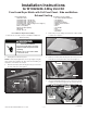

Installation Instructions
for W10323246 4-Way Vent Kit
Parts included in Kit:
1 Instruction Sheet
1 4” Diameter Vent – 305 mm (12”)
1 4” Diameter Vent – 187 mm (7.40”)
1 4” Diameter Vent – 86 mm (3.40”)
1 4” Diameter Vent – Elbow (0 degrees to 90 degrees)
2 4 3/16” Diameter Clamp
2 Plate, Cover (Metal)
2 Plugs, Side Panel (Plastic)
1 Ring, Vent
2 Screw - #8 x 1/2”
Front Load Dryer Match with Full Front Panel - Side and Bottom
Exhaust Venting
(continued)
Instruction Sheet W10337809 Rev. C 12/11
1. Unplug dryer or disconnect power.
NOTE: For Gas Dryer application, turn off gas supply using the
shut-off valve that supplies the dryer. Disconnect flexible gas
supply line connected to rear of dryer.
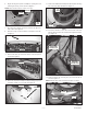
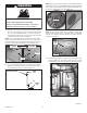
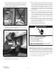
2. Remove dryer top by first removing the two (2) screws from
the rear of the dryer. See Figure 1.
WARNING
Electrical Shock
Hazard
Disconnect power before servicing.
Failure to do so can result in death
or electrical shock.
Replace all parts and panels before
operating.
figure 1
— 1 —
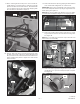
Tool and Accessories required:
• 1/4” Socket and Ratchet Wrench
• 1/4” Nut Driver
• 5/16” Nut-Driver
• Flat-Head Screwdriver
• Phillips-Head Screwdriver
• Hammer
• Pliers
• 1/8” Drill Bit
• Drill
• Cold Chisel
• File, Round
Procedure for Dryer Disassembly
To Gain Access to Inside of Dryer for Installation of Optional
Exhaust Venting
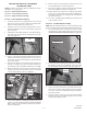
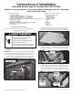
3. Remove dryer top by sliding top toward rear of dryer and lift
to remove. See Figure 2.
figure 2
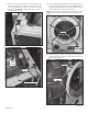
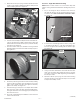
4. Remove console by first removing two (2) screws (one from
each side of console) at location as shown in Figure 3.
figure 3
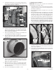
5. Disconnect drum light and main console connectors as shown
in Figure 4 located on top right front side of dryer. Lift up on
console and tilt assembly forward to remove console.
figure 4